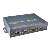
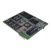
Development Kit
20 XPort™ Integration Guide
Note: During a Telnet connection, CP1 LED (LED1) is ON. For a serial port
connection, CP1 LED (LED 1) blinks for 2 seconds, then OFF for
2 seconds. (It appears as 4 blinks, then OFF for 2 seconds)
CTS and RTS work together for hardware flow control. Configure CP3 as RTS when
CP1 is configured as CTS. Select hardware flow control as described in Flow in the
XPort User Guide.
See the Device Installer User Guide for information on configuring CP3 as IN3 or
OUT3. JP4 can be used to monitor XPort pins 6 (CP1), 7 (CP2), and 8 (CP3). You
can also use it to connect external circuitry or LEDs to the evaluation board.
Figure 3-7. JP4 Configurable Pins Interface Header Footprint
JP4
1
2
35
46
Table 3-5. JP4 Connections
JP4 Pin # Connects To
1 3.3V
2 XPort pin 7, CP2
3 Signal ground
4 XPort pin 6, CP1
5 External reset – XPort pin 3
6 XPort pin 8, CP3
Timer
The timer circuit is a National LMC555 IC. Its purpose is to generate a timer clock
(approximately 10 counts per second). This clock is routed to the input clock pin of
the PLD to be used for state machine and counter functions.
 Loading...
