Description and Specifications
XPort™ Integration Guide 7
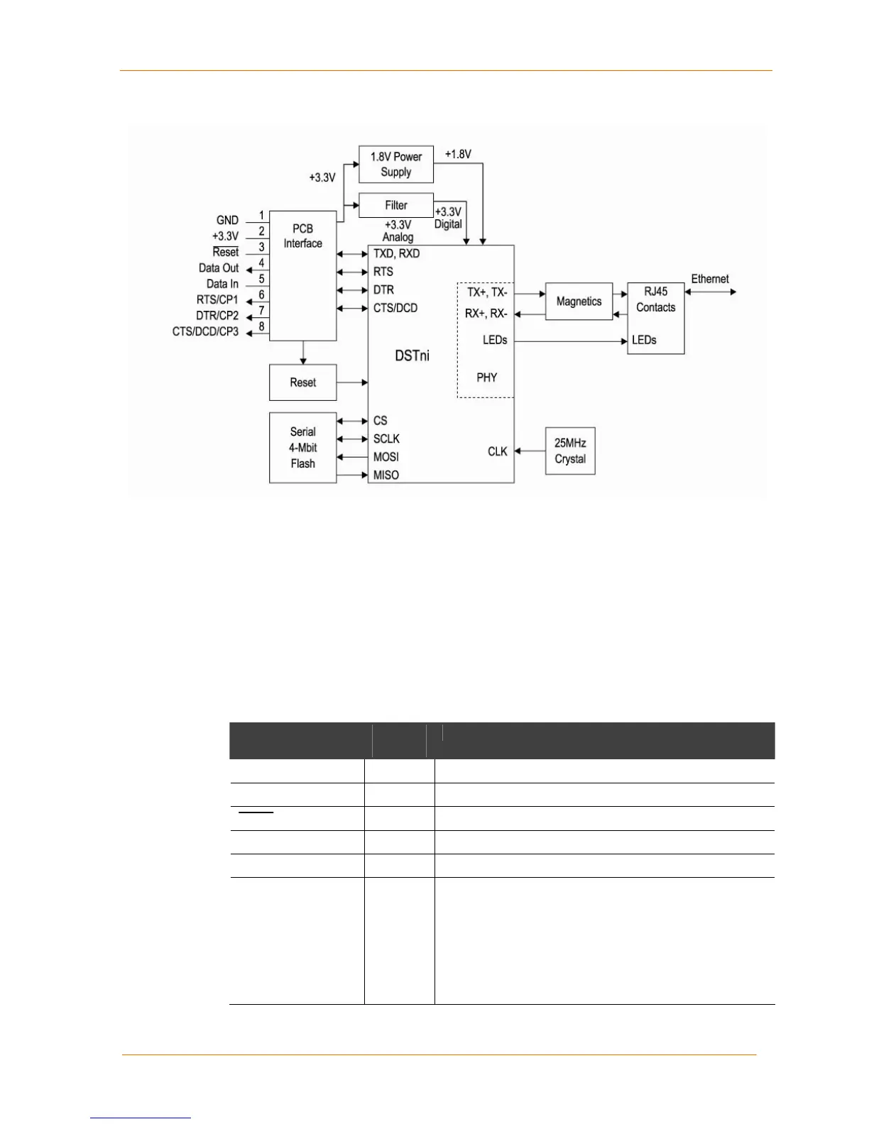
Figure 2-2. XPort Block Diagram
PCB Interface
The XPort has a serial port compatible with data rates up to 920 kbps (in high-
performance mode) for the XPort-03 and greater, and at 230 kbps for the XPort-01.
The serial signals (pins 4–8) are 3.3V CMOS logic level (5V tolerant for the XPort-03
and greater only). The serial interface pins include +3.3V, ground, and reset. The
serial signals usually connect to an internal device, such as a UART. For
applications requiring an external cable running with RS-232 or RS422/485 voltage
levels, the XPort must interface to a serial transceiver chip. We supply an RS-232
transceiver on the XPort Evaluation Board for this purpose. There is an XPort option
available for interfacing with RS422/485.
Table 2-1. PCB Interface Signals
Signal Name XPort
Pin #
Primary Function
GND 1 Circuit ground
3.3V 2 +3.3V power in
Reset 3 External reset in
Data Out 4 Serial data out (driven by DSTni’s built-in UART)
Data In 5 Serial data in (read by DSTni’s built-in UART)
CP1/RTS
(Configurable Pin 1)
6 CP1 can be configured as follows:
• Flow control: RTS (Request to Send) output driven
by DSTni’s built-in UART for connection to CTS of
attached device.
• Programmable input/output: CP1 can be driven or
read through software control, independent of serial
port activity.
 Loading...