4 XPort™ Integration Guide
List of Figures
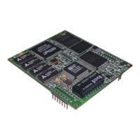
Figure 2-1. Side View of the -03 XPort ...................................................................................6
Figure 2-2. XPort Block Diagram ............................................................................................7
Figure 2-3. XPort LEDs...........................................................................................................9
Figure 2-4. Front View ..........................................................................................................10
Figure 2-5. Bottom View .......................................................................................................10
Figure 2-6. Side View............................................................................................................10
Figure 2-7. PCB Layout ........................................................................................................11
Figure 2-8. Product Label ....................................................................................................12
Figure 3-1. SW1-2 OFF ........................................................................................................17
Figure 3-2. SW1-2 ON ..........................................................................................................18
Figure 3-3. SW1-3 OFF ........................................................................................................18
Figure 3-4. SW1-3 ON ..........................................................................................................18
Figure 3-5. SW1-5 OFF and SW1-4 ON...............................................................................19
Figure 3-6. SW1-5 ON and SW1-4 ON.................................................................................19
Figure 3-7. JP4 Configurable Pins Interface Header Footprint.............................................20
Figure 3-8. Board Layout ......................................................................................................21
List of Tables
Table 2-1. PCB Interface Signals............................................................................................7
Table 2-2. Ethernet Interface Signals (Industry Standards)....................................................9
Table 2-3. XPort LED Functions (XPort-03 and greater only).................................................9
Table 2-4. Technical Specifications ......................................................................................12
Table 3-1. RS-232 Signals....................................................................................................15
Table 3-2. Configuration Switch Settings..............................................................................17
Table 3-3. CP1 Status Indicator............................................................................................18
Table 3-4. LED States...........................................................................................................19
Table 3-5. JP4 Connections..................................................................................................20
Table 3-6. Board Components..............................................................................................21
