3.2.1.
If „O.L.“ appears on the display instead of a measured value, the diode has either been tested in
the reverse direction or is faulty. If 0.0 V is measured, the diode is faulty or a short-circuit has occurred.
Forward direction
BlackBlackRed Red
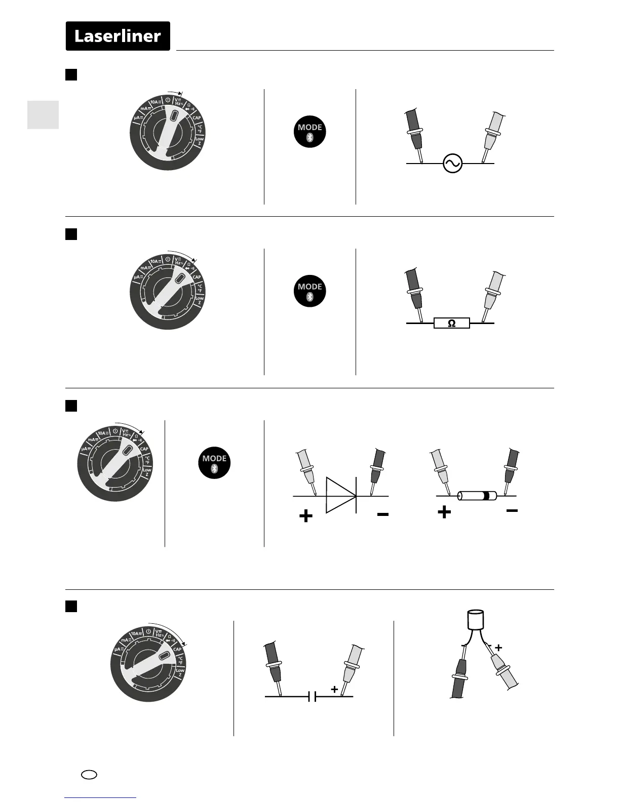
Frequency and duty factor measurements
6
Hz / % Connect the measuring contacts
to the object to be tested
RedBlack
AC, DC, Hz
and % selection
Resistance measurement
7
RedBlack
Connect the measuring contacts
to the object to be tested
Ω, continuity
check and diode
check selection
Diode test
8
Diode test
Ω, continuity
check and diode
check selection
Capacitance measurement
9
Capacitance measurement Connect the measuring contacts
to the object to be tested
In the case of poled capacitors,
connect the positive pole to
the red test prod.
RedBlack
EN
 Loading...