LAUNCH 440(440W) 455(455W) Installation Manual
10
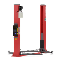
前梁
后梁
Fig.8
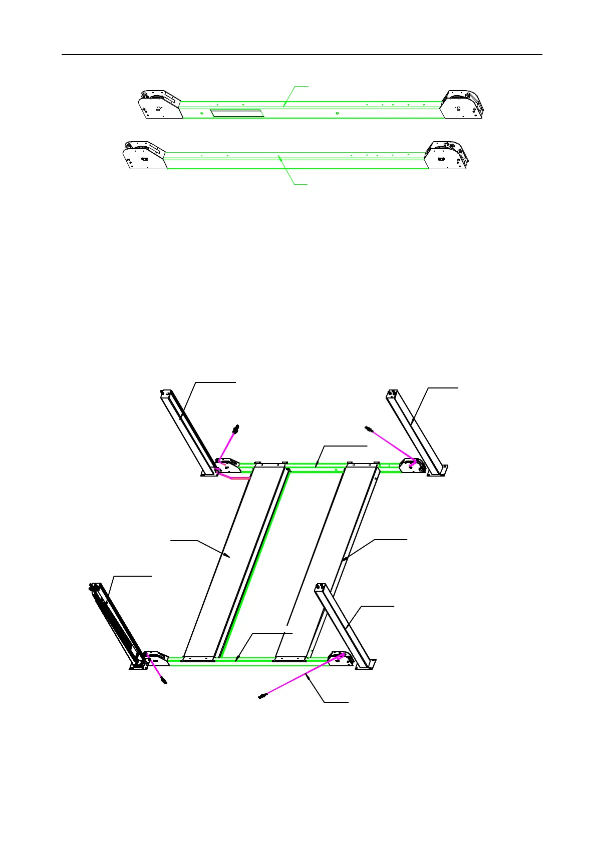
5.2.4 Position columns and locking latch plates
l Place the power unit column at the FL (front left) corner
of the lift. The hydraulic cylinder connection in the left
runway should be visible from this corner. Position other
three columns.(Fig.9)
l Thread the jam nut down the threaded stud of locking
latch plate as far as possible. Place the latch plate in the
back of the column (Fig.4). The latch plate should be
oriented toward the back of the column from the centre
line of the threaded stud.
l Place the FRL (filter, regulator and lubricator) bracket on
the power unit column.
l Threaded the adjustment nut down the threaded stud
until the nut and the top plate are flush, repeat for other
columns.
FLColumn
FRColumn
LeftRunway RightRunway
RLColumn
RRColumn
Cable
FrontCrossTube
RearCrossTube
Fig.9
www.diagtools.eu, Pernavas 43A, Riga, Latvia, LV-1009, +37129416069, info@diagtools.eu
 Loading...