LAUNCH 440(440W) 455(455W) Installation Manual
13
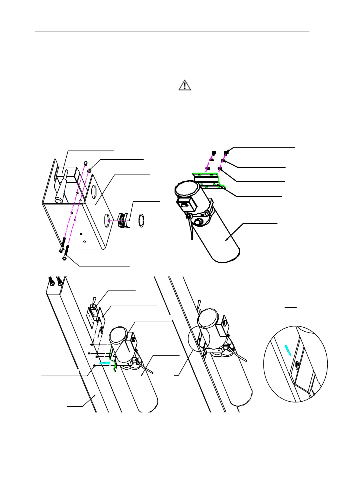
5.2.7 Install the Power Unit, hydraulic lines
l Install the hydraulic unit on the bracket with 2 M10X25
bolts and washers (Fig.13B). Using 2 M4X35
screws to install the control air valve on the bracket
(Fig.13A).
l Install the power unit with its bracket on the FL column
(Fig.13C).
l Install the control air valve with its bracket on the FL
column. (Fig.13C)
l Install the hydraulic lines and fasten all the fittings so
that no leakage will occur.(Fig.14)
l Fill the tank with enough hydraulic oil (10L). Keep
dust and other pollutants away from the oil tank
l Fix the pipes with clips as illustrated.
Cautions:
¨ Get rid off the foreign substance in the hoses and
uncover the plug of cylinder.
¨ If the hose need to go through the columns, make
sure that they do not come into contact with any
moving parts
ManualControlAirValve
2-NutM4GB/T889-86
AirValveBracket
AirConnector
2-ScrewM4*35GB/T818-85
A
ScrewM10*25GB/T5780-86
Washer10GB/T93-87
Washer10GB/T95-85
PowerUnitBrachet
PowerUnit
B
A
A
3:1
ControlAirValve
AirValveBracket
PowerUnitBracket
PowerUnit
ScrewM6*12GB/T5789-86
Column
C
www.diagtools.eu, Pernavas 43A, Riga, Latvia, LV-1009, +37129416069, info@diagtools.eu
 Loading...