Page 12
506044−01 06/08
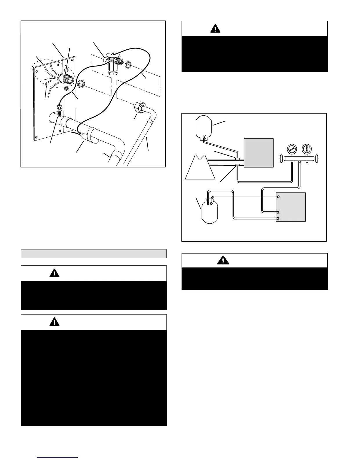
TWO PIECE
PATCH PLATE
(UNCASED COIL
ONLY)
SUCTION
LINE
DISTRIBUTOR
ASSEMBLY
DISTRIBUTOR
TUBES
LIQUID
LINE
MALE EQUALIZER
LINE FITTING
SENSING
LINE
EQUALIZER
LINE
TXV
TEFLON
RING
(Uncased Coil Shown)
STUB END
TEFLON
RING
SENSING
BULB
LIQUID LINE
ORIFICE
HOUSING
LIQUID LINE ASSEMBLY
WITH BRASS NUT
Figure 23. Typical TXV Removal
6. Disconnect the TXV from the liquid line orifice housing.
Take care not to twist or damage distributor tubes
during this process.
7. Remove and discard TXV and the two Teflon rings as
illustrated in figure 23.
8. Use a field−provided fitting to temporary reconnect the
liquid line to the indoor unit’s liquid line orifice housing.
Flushing the System
IMPORTANT
The line set and indoor unit coil must be flushed
with at least the same amount of clean refrigerant
that previously charged the system. Check the
charge in the flushing cylinder before proceeding.
IMPORTANT
If this unit is being matched with an approved line
set or indoor unit coil which was previously
charged with mineral oil, or if it is being matched
with a coil which was manufactured before
January of 1999, the coil and line set must be
flushed prior to installation. Take care to empty all
existing traps. Polyol ester (POE) oils are used in
Lennox units charged with HFC−410A refrigerant.
Residual mineral oil can act as an insulator,
preventing proper heat transfer. It can also clog
the expansion device, and reduce the system
performance and capacity.
Failure to properly flush the system per the
instructions below will void the warranty.
IMPORTANT
The Environmental Protection Agency (EPA)
prohibits the intentional venting of HFC refrigerants
during maintenance, service, repair and disposal of
appliance. Approved methods of recovery,
recycling or reclaiming must be followed.
If the original system used:
S HCFC−22 refrigerant, then flush the system using the
procedure provided in this section.
S HFC−410A refrigerant, then proceed to Installing New
Refrigerant Metering Device.
LOW
PRESSURE
HIGH
PRESSURE
EXISTING
INDOOR
UNIT
GAUGE
MANIFOLD
INVERTED HCFC−22 CYLINDER
CONTAINS CLEAN HCFC−22 TO
BE USED FOR FLUSHING.
LIQUID LINE SERVICE VALVE
INLET
DISCHARGE
TANK
RETURN
CLOSED
OPENED
RECOVERY
CYLINDER
NOTE − The inverted HCFC−22 cylinder must contain at least the same
amount of refrigerant as was recovered from the existing system.
RECOVERY MACHINE
NEW
OUTDOOR
UNIT
SUCTION LINE
SERVICE VALVE
SUCTION
LIQUID
Figure 24. Typical Flushing Connection
CAUTION
This procedure should not be performed on
systems which contain contaminants (Example:
compressor burn out).
REQUIRED EQUIPMENT
Equipment required to flush the existing line set and indoor
unit coil:
S Two clean HCFC−22 recovery bottles,
S Oilless recovery machine with pump-down feature,
S Two gauge sets (one for HCFC−22; one for
HFC−410A).
PROCEDURE
1. Connect the following:
S HCFC−22 cylinder with clean refrigerant to the
suction service valve,
S HCFC−22 gauge set to the liquid line valve,
S Recovery machine with an empty recovery tank to
the gauge set.
2. Set the recovery machine for liquid recovery and start
the recovery machine. Open the gauge set valves to
allow the recovery machine to pull a vacuum on the
existing system line set and indoor unit coil.

 Loading...