Page 24
506044−01 06/08
metal edges and corners while applying excessive
force or rapid motion can result in personal injury.
Cleaning of the outdoor unit’s coil should be performed
by a trained service technician. Contact your dealer
and set up a schedule (preferably twice a year, but at
least once a year) to inspect and service your air
conditioning or heat pump system.
THERMOSTAT OPERATION
Thermostat operations vary from one thermostat to
another. The following provides general operation
procedures. Refer to the user’s information manual
provided with your thermostat for specific operation
details.
Temperature Setting Levers Set the lever or dial to the
desired temperature setpoints for both heating and
cooling. Avoid frequent temperature adjustment; turning
the unit offthen back onbefore pressures can equalize
will put unusual stress on the unit’s compressor.
Fan Switch In AUTO or INT (intermittent) mode, the
blower operates only when the thermostat calls for heating
or cooling. This mode is generally preferred when humidity
control is a priority. The ON or CONT mode provides
continuous indoor blower operation, regardless of whether
the compressor or furnace is operating. This mode is
required when constant air circulation or filtering is desired.
System Switch Set the system switch for heating,
cooling or auto operation. The auto mode allows the
system to automatically switch from heating mode to
cooling mode to maintain predetermined comfort settings.
Temperature Indicator The temperature indicator
displays the actual room temperature.
PROGRAMMABLE THERMOSTATS
Your Lennox system may be controlled by a
programmable thermostat. These thermostats provide the
added feature of programmable time-of-day set points for
both heating and cooling. Refer to the user’s information
manual provided with your thermostat for operation
details.
PRESERVICE CHECK
If your system fails to operate, check the following before
calling for service:
S Make sure all electrical disconnect switches are ON.
S Make sure the room thermostat temperature selector
AND the system switch are properly set.
S Replace any blown fuses, or reset circuit breakers.
S Make sure unit access panels are in place.
S Make sure air filter is clean.
S Locate and record unit model number before calling.
Optional Accessories
Refer to the Lennox XC15 Engineering Handbook for the
latest available optional accessories for this unit.
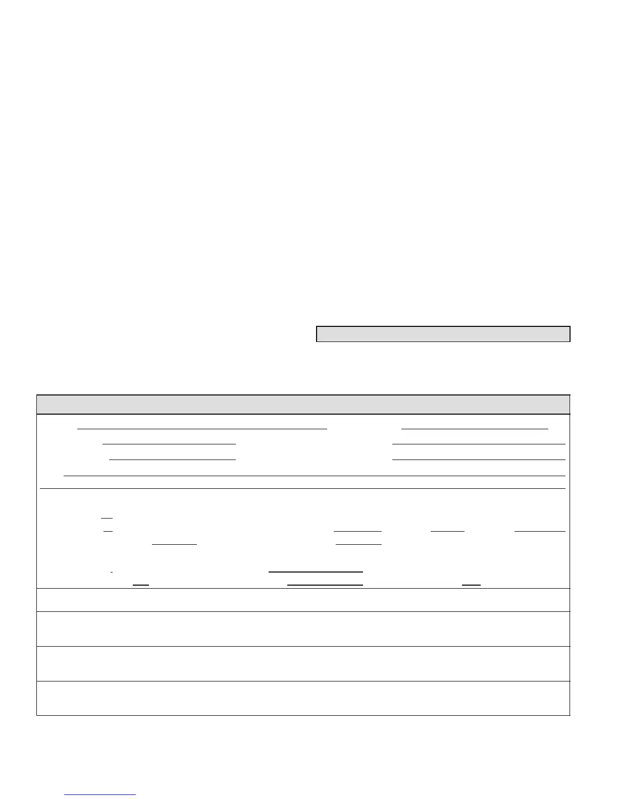
XC15 Start−Up and Performance Checklist
Customer Address
Indoor Unit Model Serial
Outdoor Unit Model Serial
Notes:
START UP CHECKS
Refrigerant Type:
Rated Load Amps Actual Amps Rated Volts Actual Volts
Condenser Fan Full Load Amps Actual Amps:
COOLING MODE
Suction Pressure: Liquid Pressure:
Supply Air Temperature: Ambient Temperature: Return Air: Temperature:
System Refrigerant Charge (Refer to manufacturer’s information on unit or installation instructions for required subcooling and approach
temperatures.)
Subcooling:
A B = SUBCOOLING
Saturated Condensing Temperature (A)
minus Liquid Line Temperature (B)
Approach:
A B = APPROACH
Liquid Line Temperature (A)
minus Outdoor Air Temperature (B)
Indoor Coil Temperature Drop (18 to 22°F) A B = COIL TEMP DROP
Return Air Temperature (A)
minus Supply Air Temperature (B)

 Loading...