Page 8
506044−01 06/08
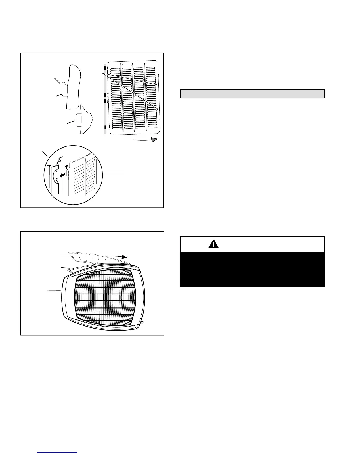
INSTALLING PANEL
Install unit at a minimum of four inches above the surface
of the roof. Care must be taken to ensure weight of unit is
properly distributed over roof joists and rafters.
DETAIL A
DETAIL B
ROTATE IN THIS DIRECTION; THEN DOWN TO REMOVE PANEL
SCREW
HOLES
LIP
IPANEL SHOWN SLIGHTLY ROTATED TO ALLOW TOP TAB TO EXIT (OR ENTER) TOP
SLOT FOR REMOVING (OR INSTALLING) PANEL.
Figure 14. Removing/Installing Louvered
Panels (Details A, B and C)
DETAIL C
IMPORTANT! DO NOT ALLOW
PANELS TO HANG ON UNIT BY TOP
TAB. TAB IS FOR ALIGNMENT AND
NOT DESIGNED TO SUPPORT
WEIGHT OF PANEL.
MAINTAIN MINIMUM PANEL ANGLE (AS CLOSE TO PARALLEL WITH THE UNIT
AS POSSIBLE) WHILE INSTALLING PANEL.
PREFERRED ANGLE
FOR INSTALLATION
ANGLE MAY BE
TOO EXTREME
HOLD DOOR FIRMLY TO THE
HINGED B SIDE TO MAINTAIN
FULLY−ENGAGED TABS
Figure 15. Removing/Installing Louvered
Panels (Detail D)
DETAIL D
Install the louvered panels as follows:
1. Position the panel almost parallel with the unit as
illustrated in figure 15, detail D with the screw side as
close to the unit as possible.
2. With a continuous motion slightly rotate and guide the
lip of top tab inward as illustrated in figure 14, details
A and C, then upward into the top slot of the hinge
corner post.
3. Rotate panel to vertical to fully engage all tabs.
4. Holding the panel’s hinged side firmly in place, close
the right−hand side of the panel, aligning the screw
holes.
5. When panel is correctly positioned and aligned, insert
the screws and tighten.
New or Replacement Line Set
This section provides information on installation or
replacement of existing line set. If line set are not being
installed then proceed to Brazing Connections on page 9.
If refrigerant lines are routed through a wall, seal and
isolate the opening so vibration is not transmitted to the
building. Pay close attention to line set isolation during
installation of any HVAC system. When properly isolated
from building structures (walls, ceilings. floors), the
refrigerant lines will not create unnecessary vibration and
subsequent sounds.
REFRIGERANT LINE SET
Field refrigerant piping consists of liquid and suction lines
from the outdoor unit (braze connections) to the indoor unit
coil (flare or sweat connections). Use Lennox L15 (sweat,
non−flare) series line set, or use field−fabricated refrigerant
lines as listed in table 2.
MATCHING WITH NEW OR EXISTING INDOOR COIL
AND LINE SET
IMPORTANT
Matching XC15 with a New Indoor Coil and Line
SetIf installing a new indoor coil and reusing the
existing line set that included a RFCI liquid line
(small bore liquid line used as a metering device)
then you must change to a standard size liquid line.
NOTE − When installing refrigerant lines longer than 50
feet, see the Lennox Refrigerant Piping Design and
Fabrication Guidelines, or contact Lennox Technical
Support Product Applications for assistance. To obtain the
correct information from Lennox, be sure to communicate
the following points:
S Model (XC15) and size of unit (e.g. −060).
S Line set diameters for the unit being installed as listed
in table 2 and total length of installation.
S Number of elbows and if there is a rise or drop of the
piping.

 Loading...