Page 19
XC15 SERIES
Table 4. HFC−410A Temperature (°F) − Pressure (Psig)
°F Psig °F Psig °F Psig °F Psig °F Psig °F Psig °F Psig °F Psig
32 100.8 48 137.1 63 178.5 79 231.6 94 290.8 110 365.0
125 445.9
141 545.6
33 102.9 49 139.6 64 181.6 80 235.3 95 295.1 111 370.0 126 451.8 142 552.3
34 105.0 50 142.2 65 184.3 81 239.0 96 299.4 112 375.1 127 457.6 143 559.1
35 107.1 51 144.8 66 187.7 82 242.7 97 303.8 113 380.2 128 463.5 144 565.9
36 109.2 52 147.4 67 190.9 83 246.5 98 308.2 114 385.4 129 469.5 145 572.8
37 111.4 53 150.1 68 194.1 84 250.3 99 312.7 115 390.7 130 475.6 146 579.8
38 113.6 54 152.8 69 197.3 85 254.1 100 317.2 116 396.0 131 481.6 147 586.8
39 115.8 55 155.5 70 200.6 86 258.0 101 321.8 117 401.3 132 487.8 148 593.8
40 118.0 56 158.2 71 203.9 87 262.0 102 326.4 118 406.7 133 494.0 149 601.0
41 120.3 57 161.0 72 207.2 88 266.0 103 331.0 119 412.2 134 500.2 150 608.1
42 122.6 58 163.9 73 210.6 89 270.0 104 335.7 120 417.7 135 506.5 151 615.4
43 125.0 59 166.7 74 214.0 90 274.1 105 340.5 121 423.2 136 512.9 152 622.7
44 127.3 60 169.6 75 217.4 91 278.2 106 345.3 122 428.8 137 519.3 153 630.1
45 129.7 61 172.6 76 220.9 92 282.3 107 350.1 123 434.5 138 525.8 154 637.5
46 132.2 62 175.4 77 224.4 93 286.5 108 355.0 124 440.2 139 532.4 155 645.0
47 134.6 78 228.0 109 360.0 140 539.0
Table 5. Normal Operating Pressures (Liquid +10 and Suction +5 psig)
IMPORTANT
Use this table to perform maintenance checks; it is not a procedure for charg-
ing the system. Minor variations in these pressures may be due to differences
in installations. Significant deviations could mean that the system is not prop-
erly charged or that a problem exists with some component in the system.
Model −024 −030 −036 −042 −048 −060
°F (°C)** Liquid Suction Liquid Suction Liquid Suction Liquid Suction Liquid Suction Liquid Suction
65 (18.3) 238 139 246 138 251 133 261 144 224 129 242 131
70 (21.1) 256 139 265 139 270 134 281 145 241 130 262 132
75 (23.9) 275 140 287 140 291 134 303 146 259 131 282 134
80 (26.7) 296 141 307 141 312 134 326 147 279 133 303 135
85 (29.4) 319 142 330 142 335 136 350 148 301 134 326 136
90 (32.2) 342 142 354 143 359 137 376 149 323 135 349 137
95 (35.0) 366 143 379 144 384 138 402 150 347 137 372 138
100 (37.8) 392 144 404 144 411 140 430 151 372 138 397 140
105 (40.6) 418 146 432 145 438 141 459 152 397 140 422 141
110 (43.3) 448 146 461 147 468 143 490 153 422 141 448 143
115 (46.1) 480 147 491 148 501 144 525 154 449 143 475 146
* These are typical pressures only. Indoor match up, indoor air quality, and indoor load will cause the pressures to vary.
** Temperature of air entering outdoor coil.
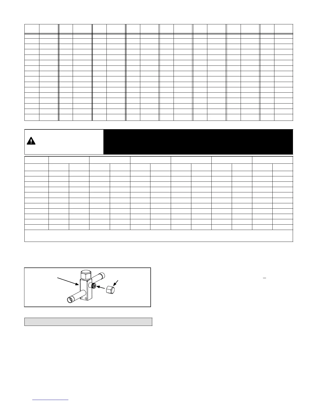
INSTALLING SERVICE VALVE CAPS
Disconnect gauge set and re−install both the liquid and
suction service valve caps.
INSTALL CAPS
OUTDOOR UNIT
SERVICE VALVE
Figure 36. Installing Service Valve Port Caps
System Operation
The outdoor unit and indoor blower cycle on demand from
the room thermostat. When the thermostat blower switch
is in the ON position, the indoor blower operates
continuously.
HIGH PRESSURE SWITCH
XC15 units are equipped with a high-pressure switch that
is located in the liquid line of the compressor as illustrated
in Unit Dimensions on page 2.
The switch is a Single Pole, Single Throw (SPST),
manual−reset switch which is normally closed and
removes power from the compressor when discharge
pressure rises above factory setting at 590 + 10 psi. The
manual−reset switch can be identified by a red cap that is
press to reset the module.
LOW PRESSURE SWITCH
XC15 units are equipped with a low pressure switch that is
located in the suction line to the compressor as illustrated
in Unit Dimensions on page 2. The switch is a Single Pole,
Single Throw (SPST), auto−reset switch that is normal
closed. The switch opens at 40 psi and closes at 90 psi.
FILTER DRIER
A drier is factory−installed in each XC15 unit as illustrated
in Unit Dimensions on page 2. A replacement drier is
available from Lennox. Refer to Lennox Repair Part
Program.

 Loading...