Page 21
XC15 SERIES
compressor to run. The yellow LED will begin flashing
a code 8 indicating a welded contactor.
3. Disconnect power from the compressor and 24VAC
power from the LSOM. While the LSOM is off, reattach
the wire to the Y terminal.
4. Reapply power to the compressor and 24VAC power
to the LSOM; the yellow LED will flash the previous
code for 60 seconds and then turn off. If the yellow
LED does not function as described, refer to table 7 to
verify the wiring.
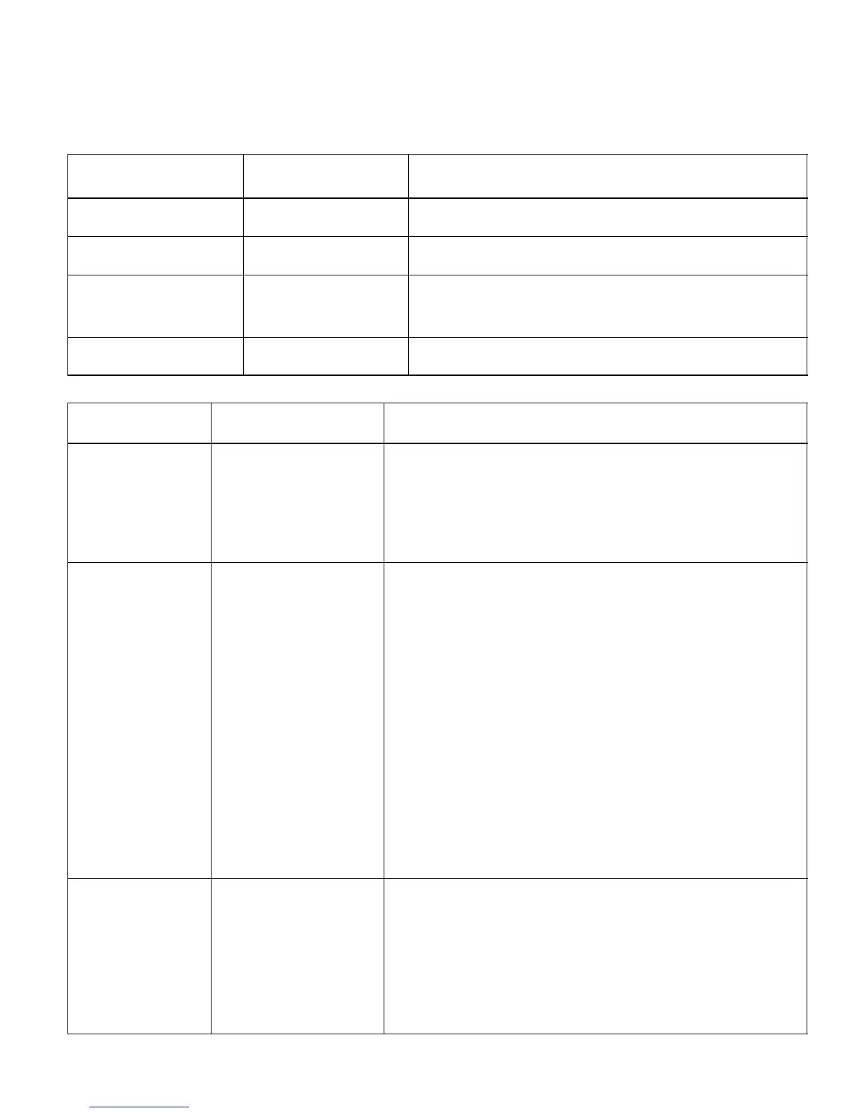
Table 7. LSOM Module LED Troubleshooting Codes
Status LED Condition
Mis−wired Module
Indication
Status LED Troubleshooting Information
Green LED ON Module not powering up.
Determine/verify that both R and C module terminals are connected and
voltage is present at both terminals.
Green LED Intermittent
Module powers up only when
compressor runs.
Determine if R and Y terminals are wired in reverse. Verify module’s R and C
terminals have a constant source.
Red LED ON
LED is on but system and
compressor check OK.
1
Verify Y terminal is connected to 24VAC at contactor coil.
2
Verify voltage at contactor coil falls below 0.5VAC when off.
3
Verify 24VAC is present across Y and C when thermostat demand signal is
present; if not present, R and C wires are reversed.
Red and Yellow LED Simultaneous flashing.
Indicates that the control circuit voltage is too low for operation. Verify R and C
terminals are supplied with 19−28VAC.
Table 8. LSOM System LED Troubleshooting Codes
Status LED
Condition
Status LED Description Status LED Troubleshooting Information
Red LED ON
Thermostat demand signal Y1 is
present, but compressor not
running
1
Compressor protector is open.
S Check for high head pressure
S Check compressor supply voltage
2
Outdoor unit power disconnect is open.
3
Compressor circuit breaker or fuse(s) is open.
4
Broken wire or connector is not making contact.
5
Low or high pressure switch open if present in the system.
6
Compressor contactor has failed to close.
Yellow Flash Code 1
Long Run Time − Compressor is
running extremely long run
cycles.
1
Low refrigerant charge.
2
Evaporator blower is not running.
S Check blower relay coil and contacts
S Check blower motor capacitor
S Check blower motor for failure or blockage
S Check evaporator blower wiring and connectors
S Check indoor blower control board
S Check thermostat wiring for open circuit
3
Evaporator coil is frozen.
S Check for low suction pressure
S Check for excessively low thermostat setting
S Check evaporator airflow (coil blockages or return air filter)
S Check ductwork or registers for blockage.
4
Faulty metering device.
S Check TXV bulb installation (size, location and contact)
S Check if TXV is stuck closed or defective
5
Condenser coil is dirty
.
6
Liquid line restriction (filter drier blocked if present)
.
7
Thermostat is malfunctioning
.
S Check thermostat sub−base or wiring for short circuit
S Check thermostat installation (location and level)
Yellow Flash Code 2
System Pressure Trip −
Discharge or suction pressure
out of limits or compressor
overloaded
1
High head pressure.
S Check high pressure switch if present in system
S Check if system is overcharged with refrigerant
S Check for non−condensable in system
2
Condenser coil poor air circulation (dirty, blocked, damaged).
3
Condenser fan is not running.
S Check fan capacitor
S Check fan wiring and connectors
S Check fan motor for failure or blockage
4
Return air duct has substantial leakage.

 Loading...