Page 12
I-UNIT COMPONENTS
The ELS parts arrangements are shown on pages 5 - 10
and control boxes on page 11.
WARNING
ELECTROSTATIC
DISCHARGE
(ESD)
Precautions and
Procedures
Electrostatic discharge can affect
electronic components. Take care
during unit installation and service to
protect the unit’s electronic controls.
Precautions will help to avoid control
exposure to electrostatic discharge
by putting the unit, the control and the
technician at the same electrostatic
potential. Touch hand and all tools
on an unpainted unit surface before
performing any service procedure to
neutralize electrostatic charge.
A-CONTROL BOX COMPONENTS
1 - Transformer T1 & T18
All ELS models use a single line voltage to 24VAC trans-
former mounted in the control box. Transformer T1 sup-
plies power to control circuits in the ELS unit. The trans-
former is rated at 70VA and is protected by a 3.5 amp
circuit breaker (CB8). CB8 is internal to the transformer.
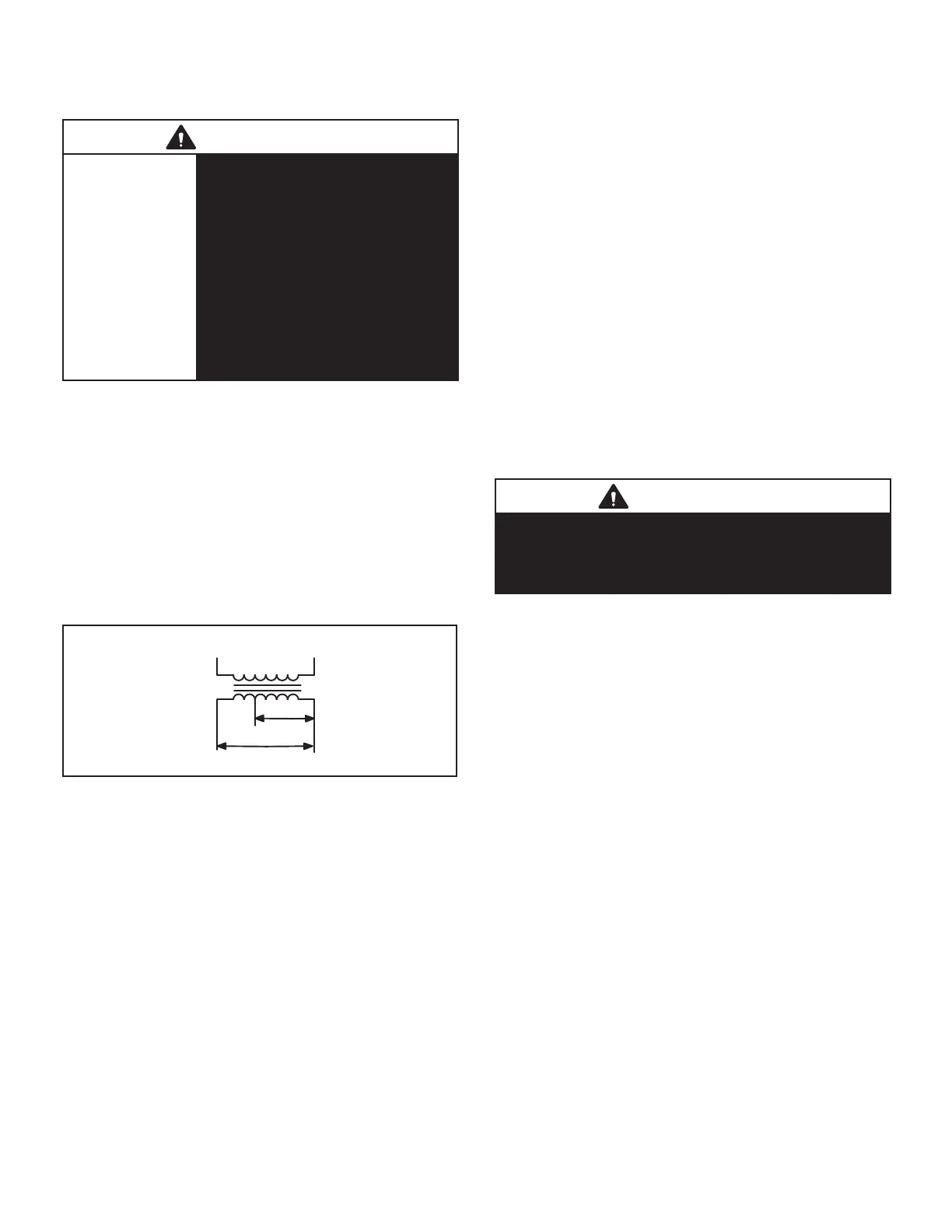
The 208/230 (Y) voltage transformers use two primary
voltage taps as shown in gure 1, while 460 (G) and 575
(J) voltage transformers use a single primary voltage tap.
T18 is identical to T1 used in ELS120, 150, 180 and 240
and is protected by internal circuit breaker CB18.
BLUE YELLOW
RED
230 VOLTS
208 VOLTS
PRIMARY
SECONDARY
FIGURE 1
NOTE – 208 volt units are eld wired with the red wire
connected to control transformer. 230 volt units are factory
wired with the orange wire connected to control transfo-
mer primary.
2 - Terminal Strip TB14 & TB2
Terminal strip TB14 used in all units distributes 24V power
and common from the transformer T18 to the control box
components. Terminal block TB2 used in the 120, 150,
180 and 240 units, distributes line voltage to line voltage
components.
3 - Condenser Fan Capacitors C1, C2, C18, C19
All ELS units use single-phase condenser fan motors. Mo-
tors are equipped with a fan run capacitor to maximize
motor efciency. Condenser fan capacitors C1, C2, C18
and C19 assist in the start up of condenser fan motors B4,
B5, B21 and B22. Capacitor ratings will be on condenser
fan motor nameplate.
4 - Compressor Contactor K1 (all units) K2 (120S4D,
150, 180, 240)
All compressor contactors are three-pole double-break
contactors with auxiliary switch with a 24V coil. In
ELS072, 090 and 120S4S, K1 energizes compressor B1.
In ELS120S4D, 150, 180 and 240 units, K1 and K2 ener-
gize compressors B1 and B2.
5 - Condenser Fan Relay K10 (all units) K149 (180, 240)
Condenser fan relays K10 and K149 are DPDT with a 24V
coil. In all units K10 energizes condenser fan B4 (fan 1) in
response to thermostat demand. In the ELS120S4D, 150,
180 and 240, K10 also energizes condenser fan B5 (fan 2)
In the ELS180 and 240 K149 energizes condenser fans B21
(fan 3) and B22 (fan 4) in response to thermostat demand.
6 - Cooling Relays K66 (120S4D, 150, 180, 240) & K67
(all units)
Cooling relays K66 and K67 are N.O. DPDT relays. K66
is energized from ”Y1” (1st stage cool), which in turn en-
ergizes contactor K2. K67 is energized by ”Y2” (2nd stage
cool), which in turn energizes contactor K1. This sequence
is the start up of compressors B1 and B2.
B-COOLING COMPONENTS
WARNING
Refrigerant can be harmful if it is inhaled. Refrigerant
must be used and recovered responsibly.
Failure to follow this warning may result in personal
injury or death.
1 - Compressor
ALL ELS model units use scroll compressors. ELS072,
ELS090 and ELS120S4S models have one two-stage scroll
compressor. ELS120S4D, ELS150S4D, ELS180S4D and
ELS240S4D models have two single-stage scroll com-
pressors.
Compressor consists of two involute spiral scrolls matched
together to generate a series of crescent shaped gas
pockets between them.
During compression, one scroll remains stationary while
the other scroll orbits around it.
Gas is drawn into the outer pocket, the pocket is sealed as
the scroll rotates.
As the spiral movement continues, gas pockets are
pushed to the center of the scrolls. Volume between the
pockets is simultaneously reduced.
When pocket reaches the center, gas is now high pres-
sure and is forced out of a port located in the center of the
xed scrolls.
During compression, several pockets are compressed si-
multaneously resulting in a smooth continuous compres-
sion cycle.
Continuous ank contact, maintained by centrifugal force,
minimizes gas leakage and maximizes efciency.
Scroll compressor is tolerant to the effects of slugging and
contaminants. If this occurs, scrolls separate, allowing liq-
uid or contaminants to be worked toward the center and
discharged.
 Loading...