Page 18
WARNING
Possible equipment damage.
Avoid deep vacuum operation. Do not use compressors
to evacuate a system. Extremely low vacuum can cause
internal arcing and compressor failure. Damage caused
by deep vacuum operation will void warranty.
IMPORTANT
Use a thermocouple or thermistor electronic vacuum
gauge that is calibrated in microns. Use an instrument
capable of accurately measuring down to 50 microns.
Evacuating the system of non-condensables is critical for
proper operation of the unit. Non-condensables are de-
ned as any gas that will not condense under tempera-
tures and pressures present during operation of an air
conditioning system. Non-condensables and water suc-
tion combine with refrigerant to produce substances that
corrode copper piping and compressor parts.
NOTE - Remove cores from service valves if not already
done.
1 - Connect an HFC-410A manifold gauge set as
illustrated in gure 5.
2 - Open both manifold valves and start the vacuum
pump.
3 - Evacuate the line set and indoor unit to an absolute
pressure of 23,000 microns (29 inches of mercury).
NOTE - During the early stages of evacuation, it is desir-
able to close the manifold gauge valve at least once to
determine if there is a rapid rise in pressure this indicates
a relatively large leak. If this occurs, repeat the leak test-
ing procedure.
NOTE - The term absolute pressure means the total ac-
tual pressure within a given volume or system, above the
absolute zero of pressure. Absolute pressure in a vacuum
is equal to atmospheric pressure minus vacuum pressure.
4 - When the absolute pressure reaches 23,000
microns (29 inches of mercury), close the manifold
gauge valves, turn off the vacuum pump and
disconnect the manifold gauge center port hose
from vacuum pump. Attach the manifold center
port hose to a dry nitrogen cylinder with pressure
regulator set to 150 psig (1034 kPa) and purge the
hose. Open the manifold gauge valves to break the
vacuum in the line set and indoor unit. Close the
manifold gauge valves.
5 - Shut off the dry nitrogen cylinder and remove the
manifold gauge hose from the cylinder. Open the
manifold gauge valves to release dry nitrogen from
the line set and indoor unit.
6 - Reconnect the manifold gauge to vacuum pump,
turn pump on, and continue to evacuate line set and
indoor unit until the absolute pressure does not rise
above 500 microns within a 20-minute period after
shutting off vacuum pump and closing the manifold
gauge valves.
7 - When the absolute pressure requirement above has
been met, disconnect the manifold hose from the
vacuum pump and connect it to an upright cylinder
of HFC-410A refrigerant. Open the manifold gauge
valve pressure line set to break vacuum with 2 to
5 psi.
8 - Perform the following:
A - Close manifold gauge valves
B - Shut off HFC-410A cylinder
C - Reinstall service valve cores by removing manifold
hose from service valve. Quickly install cores
with core tool while maintaining a positive system
pressure.
D - Replace the stem caps and secure nger tight, then
tighten an additional one-sixth (1/6) of a turn as
illustrated in gure 2.
C-Charging
ELS units have a factory holding charge of 2 pounds of
HFC-410A in each circuit. Additional refrigerant will need
to be added during installation (table 3).
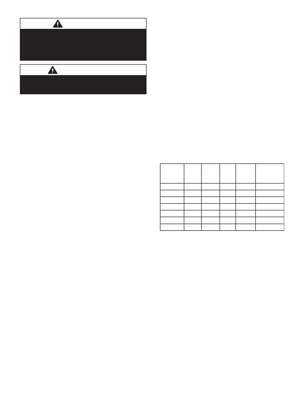
TABLE 3
Adding Refrigerant
Models
Stage 1
lbs
for 25ft
line set
Stage 2
lbs
for 25ft
line set
Liq.
Line
Dia.
Suction
Line
Dia.
Ounces
Adjustment
per foot of
line set
1
ELS072S4S 18.5N/A 3/8 1-1/8 0.7
ELS090S4S 21.75N/A 5/8 1-1/8 1.7
ELS120S4S23N/A 5/8 1-1/8 1.7
ELS120S4D12123/8 1-1/8 0.7
ELS150S4D15 15.53/8 1-1/8 0.7
ELS180S4D 23.75 23.55/8 1-1/8 1.7
ELS240S4D 22.5 23.55/8 1-1/8 1.7
1
If line set length is greater than 25 feet, add this amount
to each circuit. If line set is less than 25 feet, subtract this
amount from each circuit. Refer to Lennox Refrigerant
Piping Design and Fabrication Guidelines for more infor-
mation.
NOTE - Refrigerant line sets longer than 200 feet (60 me-
ters) are not recommended. For assistance contact Len-
nox Application Department.
To check the charge, use the following procedure:
1 - Attach gauge manifolds and operate unit in cooling
mode until system stabilizes (approximately ve
minutes). Make sure outdoor air dampers are
closed.
2 - Use a thermometer to accurately measure the
outdoor ambient temperature.
3 - Apply the outdoor temperature to tables 5 and 6 to
determine normal operating pressures.
 Loading...