Page 23
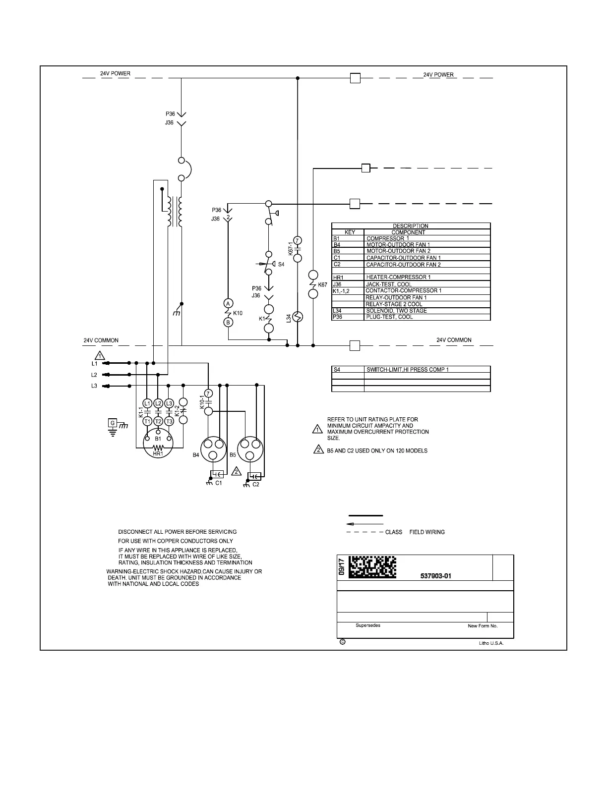
VI-Wiring Diagram and Sequence of Operation
A-ELS072-120S
ELS-072,090,120-G,J,M,Y
537903-01
4
DENOTES OPTIONAL COMPONENTS
LINE VOLTAGE FIELD INSTALLED
TB14
TERMINAL STRIP-CLASS II VOLTAGE
R
TB14
C
K10,-1
S24
SECTION A2
1
208V
T1
24V
CB8
CB8
CIRCUIT BREAKER-TRANS T1
S24
T1
SWITCH-LOSS OF CHARGE,COMP 1
TRANSFORMER-CONTROL
C1
COOL 1
2
2
1
3
1
3
6
2011
09/17
4
C2
COOL 2
240/460/575V
400V
K67-1
DUAL SPEED COMPRESSOR
REV. 0
II
WIRING DIAGRAM
1 - Cooling demand energizes at thermostat terminal
Y1. Voltage passes through N.C. loss of charge
switch S24 and N.C. high pressure switch S4.
2 - Compressor contactor K1 and outdoor fan relay
K10 are energized.
3 - K1-1 closes, energizing compressor B1 on low
speed and K10-1 closes, energizing outdoor fan
B4 and B5 in ELS120S. K1-2 opens to de-energize
crankcase heater HR1.
4 - On two-speed systems, voltage passes through
K67-1, energizes compressor solenoid L34,
switching compressor to high speed.
 Loading...