Page 13
Low gas pulses during compression reduces operational
sound levels.
Compressor motor is internally protected from excessive
current and temperature.
Compressor is installed in the unit on resilient rubber
mounts for vibration free operation.
Compressor B1 operates during all cooling demand and
is energized by contactor K1 upon receiving rst stage de-
mand. Compressor B2 operates only during second stage
cooling demand, and is energized by contactor K2. See
ELECTRICAL section or compressor nameplate for com-
pressor specications.
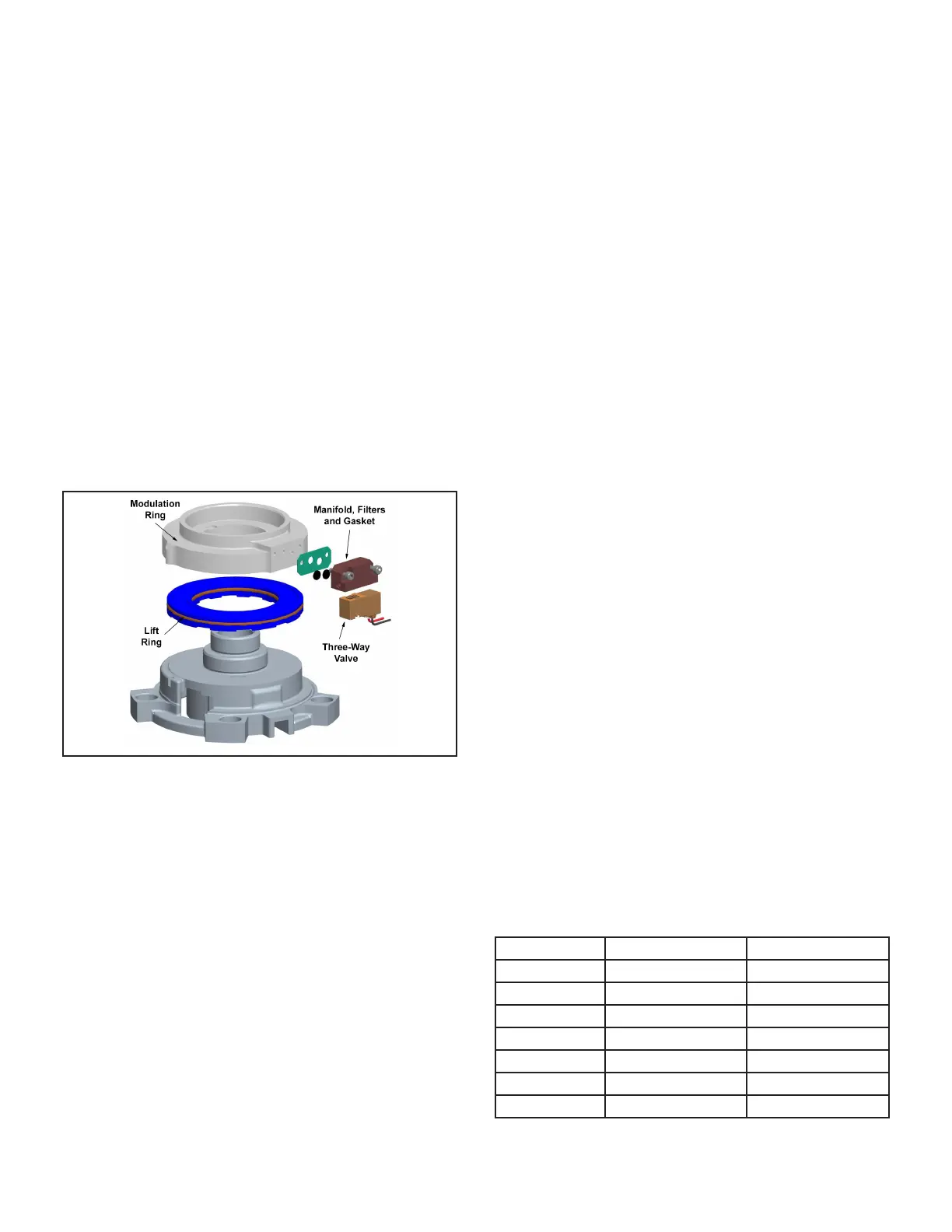
ELS072, ELS090 and ELS120S4S Two Stage Models
A 24-volt DC solenoid valve inside the compressor controls
staging. When the 3-way solenoid is energized it moves
the lift ring assembly to block the ports and the compressor
operates at full-load or 100% capacity. When the solenoid
is de-energized the lift ring assembly moves to unblock the
compressor ports and the compressor operates at part-
load or approximately 67% of its full-load capacity.
The “loading” and “unloading” of the two stage scroll is
done “on the y” without shutting off the single-speed
compressor motor between stages.
FIGURE 2. Two-Stage Scroll Compressor
2 - Crankcase Heaters HR1 (all units) and HR2
(120S4D, 150, 180, 240)
All ELS series units use a belly-band type crankcase heat-
er. Heater HR1 is wrapped around compressor B1 and
heater HR2 is wrapped around compressor B2. HR1 and
HR2 assure proper compressor lubrication at all times.
3 - High Pressure Switch S4 (all units) & S7 (120S4D,
150, 180, 240)
The high pressure switch is a manual-reset SPST N.C.
switch which opens on a pressure rise. The switch is lo-
cated in the compressor discharge line and is wired in se-
ries with the compressor contactor coil. When discharge
pressure rises to 640 + 10 psig (4413 + 69 kP ) the switch
opens and the compressor is de-energized.
4 - Filter Drier (all units)
All ELS model units have a lter drier that is located in the
liquid line of each refrigerant circuit at the exit of each con-
denser coil. The drier removes contaminants and moisture
from the system.
5 - Condenser Fan B4 (all units) B5 (120S4S,120S4D,
150, 180, 240) B21 & B22 (180, 240)
See pages 2 and 3 for the specications on the condens-
er fans used in the ELS units. All condenser fans have
single- phase motors. The ELS072 and 090 units are
equipped with a single condenser fan. The ELS120 and
150 are equipped with two fans and the 180 and 240 have
four fans. The fan assembly may be removed for servicing
by removing the fan grill, unplugging the motor then loos-
ening the motor bracket. The assembly will lift out.
6 - Loss of Charge Switch S24 & S25
The loss of charge switch is an auto-reset SPST N.C.
switch which opens on a pressure drop (almost a complete
loss of charge). All ELS units have S24 and the 120S4D
through 240 have S25. The switch is located in the liquid
line and wired in series with compressor contactor and
high pressure switch. S24 is wired in series with rst stage
cool and S25 is wired in series with second stage cool.
When pressure drops below 40+ 5 psig (indicating loss of
charge in the system) the switch opens and compressor
is de-energized. The switch automatically resets when re-
frigerant is added and pressure in the discharge line rises
above 90+ 5 psig.
7 - Head Pressure Control A190 & A191 and Pressure
Transducer A188 & A189
The low ambient kit is designed to maintain the head pres-
sure across the liquid line by varying the condenser speed
fan.
Head pressure Control A190 (all units) and A191 (ELS180,
240) is used to set the desired liquid line pressure (315
psig in ELS units). The pressure transducer A190 (All
units) A191 (120S4D through 240) measures the liquid
line pressure sending an analog signal to the head pres-
sure controller. If pressure falls below set point, the head
pressure controller reduces the fan speed to increase the
liquid line pressure to the set point.
II- REFRIGERANT SYSTEM
A-Plumbing
Field refrigerant piping consists of liquid and suction lines
connecting the condensing unit and the indoor unit. Liquid
and suction service valves are located in a compartment
at the corner of the unit below the control box. Piping can
be routed directly from the service valves or eld supplied
elbows can be added to divert the piping as required Refer
to table 1 for eld-fabricated refrigerant line sizes for runs
up to 50 linear feet (15 m).
TABLE 1
ELS Unit Liquid Line Suction Line
072 3/8" (10mm) 1-1/8" (29mm)
090 5/8" (16mm) 1-1/8" (29mm)
120S4S 5/8" (16mm) 1-1/8" (29mm)
120S4D 3/8" (10mm) 1-1/8" (29mm)
150 3/8" (10mm) 1-1/8" (29mm)
180 5/8" (16mm) 1-1/8" (29mm)
240 5/8" (16mm) 1-1/8" (29mm)
 Loading...