COMMISSIONING
FLEXYII_WSHP-IOM-0909-E Page 46
STARTING THE UNIT
At this point the unit circuit breakers should be open
You will need a DS50 maintenance controller or Adalink with
appropriate Interface.
The jumpers are factory set and the configuration switches
are adjusted depending on the option the type of unit.
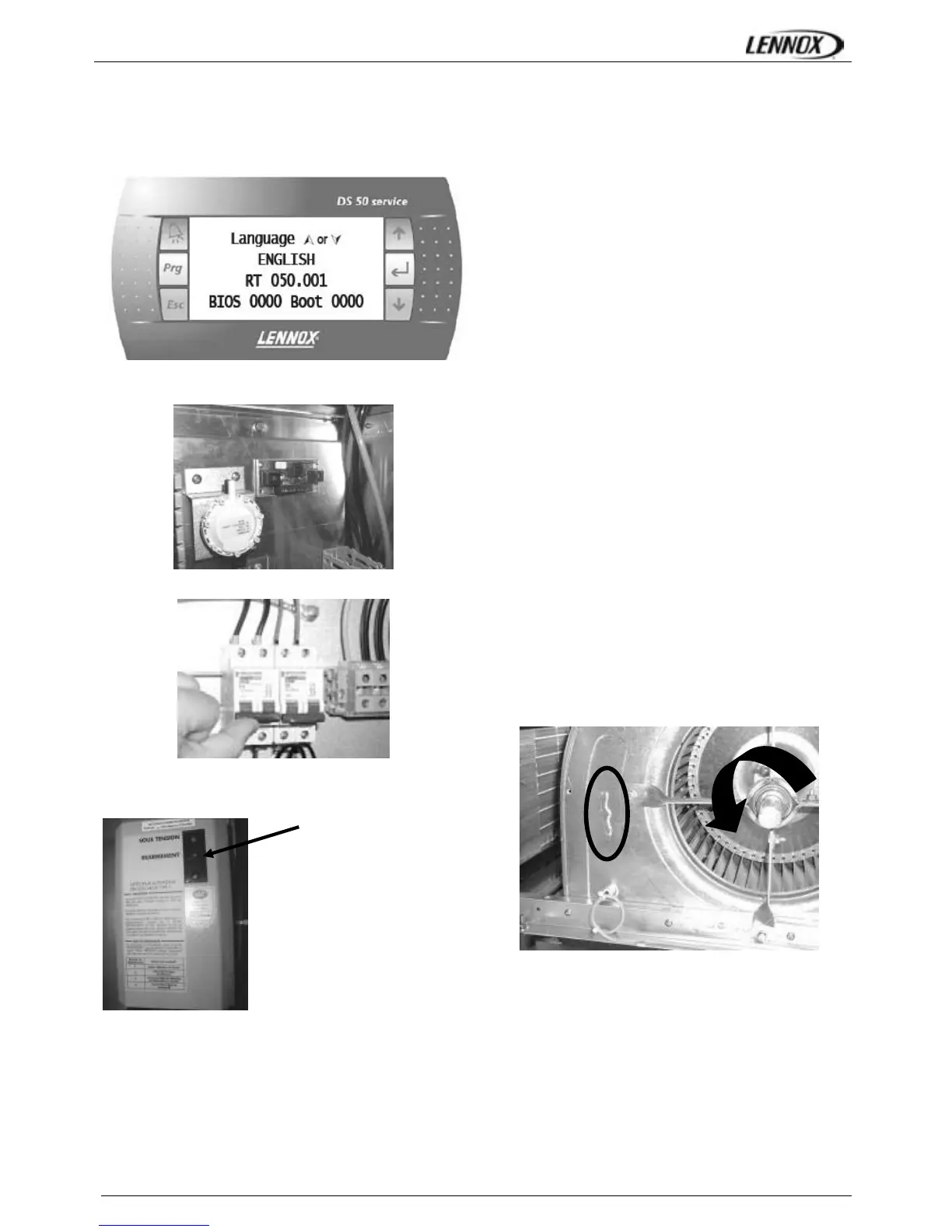
Connecting the CLIMATIC displays
Close the 24V Control Circuit breakers.
The CLIMATIC 50 starts after 30s
Reset the DAD photo (If fitted)
Check and adjust the control settings.
Refer to the control section in this manual to adjust the
different parameters.
POWERING THE UNIT
- Power up the unit by closing the isolator switch (if fitted). -
At this point the blower should start unless the climatic does
not energise the contactor. In this particular case the blower
can be forced by bridging the port NO7 and C7 on
connector J14 on the Climatic. Once the fan is running,
check the rotation direction. Refer to the rotation arrow
located on the fan.
- The fans and compressors direction of rotation is checked
during the end of line test. They should therefore all turn in
either the right or wrong direction.
NOTE: A compressor rotating in the wrong direction will fail.
- If the fan turns in the wrong direction (the right direction is
shown on figure n° 11), disconnect the main power supply
to the machine at the building's mains switch, reverse two
phases and repeat the above procedure.
- Close all circuit breakers and power up the unit, remove
the bridge on connector J14 if fitted.
- If now only one of the components rotates in the wrong
direction, disconnect the power supply at the machine's
isolator switch (if fitted) and reverse two of the component’s
phases on the terminal within the electrical panel.
- Check the current drawn against the rated values, in
particular on the supply fan (ref. page 33).
- If the readings on the fan are outside the specified limits,
this usually indicates excessive air flow which will affect the
life expectancy and the thermodynamic performances of the
unit. This will also increase the risks of water ingress into
the unit. Refer to the "Air Flow Balancing" section to correct
the problem.
At this point attach the manometers to the refrigerant circuit
Fig. 11
 Loading...