IOM – FLEXY II – 1007 – E Page 37
EXAMPLE
The unit us ed f or t his ex am ple is a F GM170ND with standard supply and return airf low conf iguration. It is also f itted with an
economiser and an electric heater type H.
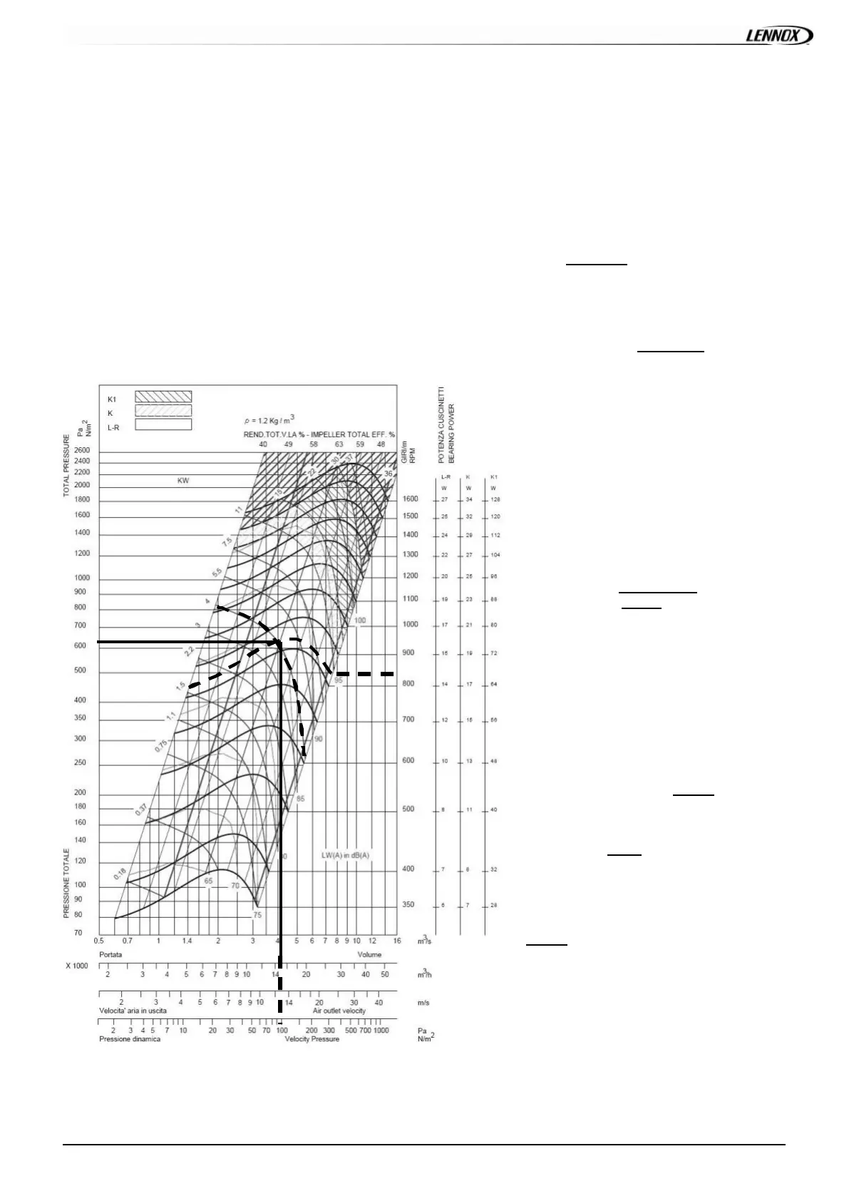
It is fitted with 2 ADH450 L f ans whic h c urv e is shown on page 36 and 2x 5.5 k W m ot ors..
- Motor rpm : 1447 rpm
- cos = 0.83
- Voltage = 400V
- Current = 9.00A (per f an)
P
mec h fa n
= V x I x 3 x cos x
mec h mot or
x
Trans mission
= 400 x 9.00 x 3 x 0.83 x 0.86 x 0.9 = 4.00kW
The unit is als o f it t e d wi t h 2 t r a ns m is s i o n k it s 3 .
- Fixed Fan pulley: 200mm
- Motor adjustable pulley ty pe “8550” opened 4 turns from fully closed or measured distance between pulley end plates is
29.1mm: from table_1 it can be determined that each motor pulley has a diameter of 114.2mm
rpm
FAN
= rpm
MOTOR
x D
M
/ D
F
= 1447 x 114.2 / 200 = 826 rpm
Using the fan curv e, the operating point can
be located.
In order to facilitate the calculation, you
won’t make any mistake by considering
that the external static pressure available
is the one calculated with one fan
providing the half of the nominal flow
(here 15000m3/h).
It can be determined that the fan is providing
approximately 15000 m3/h
with a total
pressure P
TOT
= 630 Pa
The pres s ure los s es in t he unit are the sum
of all pressure drops across the different
parts of a unit:
- Coil and f ilter (measured) = 89 Pa
- Inlet into the unit = 50 Pa
- Options = 16 Pa f or economiser and 15
Pa f or electric heater H
P = 89 + 16 + 15 +50 = 170 Pa
The dy nam ic pressure at 15000m
3
/h is given
at the bottom of the f an curve.
Pd = 81 Pa
The ex t ernal stat ic press ure av ailable is
therefore
ESP = P
TOT
- Pd - P
INT
=630 - 91 - 170 =
369 Pa
 Loading...