IOM – FLEXY II – 1007 – E Page 49
PRELIMINARY CHECKS BEFORE START-UP
NOTE :
ANY WORK ON THE GAS SYSTEM MUST BE CARRIED
OUT BY QUALIFIED PERSONNEL.
THIS UNIT MU ST BE I N STALLED IN AC C OR D AN C E
WITH LOCAL SAFETY CODES AND REGULATIONS
AND CAN ONLY BE USED IN PLANED INSTALLATION
CONDITIONS F OR OU TD OOR .
PLEASE READ CAREFULLY THE MANUFACTURER’S
INSTRUCTIONS BEFORE STARTING A UNIT.
BEFORE COMMISSIONING A UNIT WITH GAS
BURNER, IT IS MANDATORY TO ENSURE THAT THE
GAS DISTRIBUTION SY STEM (ty pe of gas, av ailable
pressure…) IS COMPATIBLE WITH THE ADJUSTMENT
AND SETTINGS OF THE UNIT.
CHECK ACCESS AND CLEARANCE AROUND THE UNI T
- Make sure one can move freely around the unit.
- A minimum one-met er clearance must be lef t in f ront of
the burnt gas exhaust flue.
- Combustion air inlet and burnt gas exhaust(s) must NOT
be obstructed in any way.
SUPPLY NETWORK PIPE SYZING
MALE THR EAD ED CONNECTION FOR GAZ BURN ER : 3/ 4”
Check that the gas supply line can provide the burners with
the pressure and the gas flow rate necessary to provide the
heating nominal output.
Number of male threaded connections (3/4”)
UNIT SIZE 85 100 120 150 170 200 230
S POWER 1 1 1 2 2 2 2
H POWER 2 2 2 2 2 2 2
GAS FLOW (for G20 at 20mbar and 15°C) m
3
/h
UNIT SIZE 85 100 120 150 170 200 230
S POWER 6.3 6.3 6.3 12.5 12.5 18.8 18.8
H POWER 12.5 12.5
12.5
18.8 18.8 25 25
For modulating gas we have just H power for F, G & H-box
- The gas supply of a Rooftop gas unit must be realized
according to Sound Engineering Practice and the local
safety codes and rules.
- In any case the diameter of pipe-work connec ted to eac h
Rooftop must not be smaller than the diameter of the
connection on the Rooftop unit.
- Make sure that a shut-of f i so l at i o n v a lv e h as b e e n
installed before EACH Rooftop.
- Check the supply voltage to the exit of the power
supply's transformer T3 of the burner: it must be between
220 and 240V.
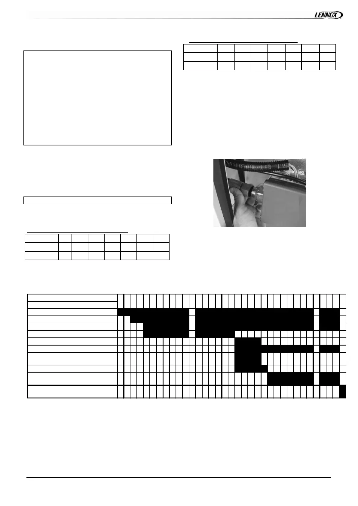
STARTING UP THE GAS BU RNER
Purge the pipe-work near t he c onnec t ion on the ignition
control Valve f or a few seconds.
- Check that the unit's treatment “Fan” blower is running.
- Set the control to “ON ” This will priorit ies t he gas burner.
- Increase the set temperature (room set point temperature) to
a temperature higher than the actual room temperature.
Table4 - Standard start-up Chronology
Time in seconds
Operations
Control operation sequence
Extract io n f an
Smo ke ext raction fan "ON"
30 to 45 seconds pre-ventilation
Fire-up spark electrode 4s
Opening of the gas valve "High Heat "
Flame propagation towards the ionisation
probe
If ionisation within 5s: Normal running
Ot herwise fault on gas ingnition cont rol
block
Af ter 5 minutes, fa ult report ed on the
climatic controller
If incorrect sequence refer to the fault analysis table to identify the problem
399
400
401
45
46
398
41
42
43
44
37
38
39
40
33
34
35
36
29
30
31
32
9
10
11
5
6
7
8
1
2
3
4
 Loading...