Page 14
The SureLight
®
integrated ignition control is equipped with
two LED lights for troubleshooting. The diagnostic codes
are listed below in table 8.
TABLE 8
DIAGNOSTIC CODES
Make sure to Identify LED’S Correctly. Refer to figure 6 or 8.
LED #1
97L48 − DIAG1 Green
69M15 − DS1 Red
LED #2
97L48 − DIAG2 Green
69M15 − DS2 Green
DESCRIPTION
SIMULTANEOUS
SLOW FLASH
SIMULTANEOUS
SLOW FLASH
Power on − Normal operation.
Also signaled during cooling and continuous fan.
SIMULTANEOUS
FAST FLASH
SIMULTANEOUS
FAST FLASH
Normal operation − signaled when heating demand initiated at thermostat.
SLOW FLASH ON
Primary or secondary limit switch open. Limit must close within 3 minutes or unit goes into 1
hour Watchgurad.
OFF SLOW FLASH
Prove Switch open
OR: Blocked inlet/exhaust vent;
OR: Prove switch closed prior to activation of combustion air blower.
OR: Blocked condensate line
ALTERNATING
SLOW FLASH
ALTERNATING
SLOW FLASH
Watchguard −− burners failed to ignite.
Limit open more than 3 minutes OR: Lost flame sense 5 times in one heating cycle.
SLOW FLASH OFF Flame sensed without gas valve energized.
ON SLOW FLASH Rollout switch open. OR: Low voltage pin connector improperly attached.
ON ON
ON OFF
Circuit board failure or control wired incorrectly. Check 120 and 24 voltage to board.
OFF ON
FAST FLASH SLOW FLASH Main power polarity reversed. Switch line and neutral. Improper main ground.
SLOW FLASH FAST FLASH
Low flame signal. Measures below:
Control 97L48 0.61 microAmps
Control 69M15 0.31 microAmps.
Replace flame sense rod.
ALTERNATING
FAST FLASH
ALTERNATING
FAST FLASH
The following conditions are sensed during the ignitor warm−up period only:
1) Improper main ground;
2) Broken ignitor; OR: Open ignitor circuit;
3) Line voltage below 75 volts.
(If voltage lower than 75 volts prior to ignitor warm-up, control will signal waiting on call from
thermostat, and will not respond.
NOTE − Slow flash rate equals 1 Hz (one flash per second). Fast flash rate equals 3 Hz (three flashes per second).
Low flame sense current − 97L48 control = 0.21−0.60 microAmps. 69M15 control = 0.25 − 0.30 microAmps.
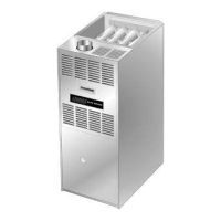
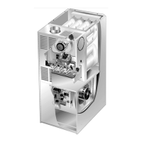
C−Heating Components
Combustion air inducer (B6), primary limit control (S10), ig-
nitor, burners, flame rollout switch (S47), gas valve (GV1),
combustion air prove switch (S18), and clamshell heat ex-
changers are located in the heating compartment. The heat-
ing compartment can be accessed by removing the burner
access panel.
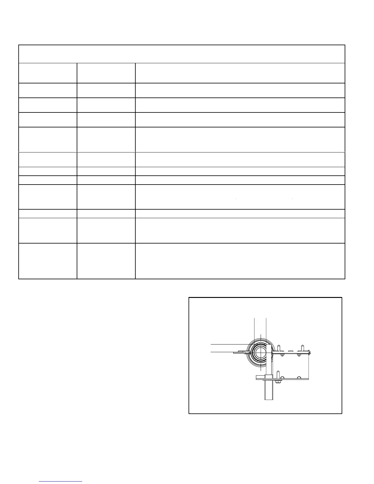
1. Ignitor (Figure 9)
The ignitor is made of durable silicon nitride. Ignitor longev-
ity is enhanced by controlling voltage to the ignitor. The igni-
tion control finds the lowest ignitor temperature which will
successfully light the burner, thus increasing the life of the
ignitor. Due to this feature of the board, voltage cannot be
measured so ignitor must be ohmed. Ohm value should be
10.9 to 19.7
FIGURE 9
13/32’
5/8"
Ignitor Location
(up flow position)
BURNERS FRONT VIEW
MEASUREMENT IS TO I.D.
OF RETENTION RING
IGNITOR
BRACKET
 Loading...