all −135
.65 (162) .55" (137) .45" (112)
NOTE − See table 22 for high altitude kits.
*Set point is factory set and non−adjustable.
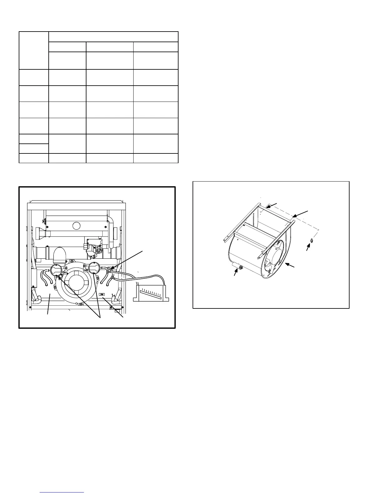
FIGURE 16
CAI & COLD END HEADER BOX ASSEMBLY
Install tee’s in the
negative line and
positive line then
connect hoses to
manometer.
prove switches
orifice size
cold end header box
+
−
+−
4 − Operate unit and observe draft gauge reading. Read-
ings will change as heat exchanger warms.
a. Take one reading immediately after start-up.
b. Take a second reading after unit has reached steady
state (approximately 5 minutes). This will be the pres-
sure differential.
The pressure differential should be greater
than those listed in table 10.
5 − Remove thermostat demand and allow to cycle off.
6 − Remove manometer and tee’s. Reinstall combustion air
sensing hoses to the prove switch.
7 − Repeat steps 1 through 6 for the other prove switch.
D−Blower Compartment (Figure 17)
Blower motor (B3) and capacitor (C4), are located in the
blower compartment. The blower compartment can be ac-
cessed by removing the blower access panel.
1.Blower Motor (B3) and Capacitor (C4)
All G51MP units use single−phase direct−drive blower mo-
tors. All motors are 120V permanent split capacitor motors to
ensure maximum efficiency. See SPECIFICATIONS table at
the front of this manual for more detail. See motor nameplate
for capacitor ratings.
2. Secondary Limit Controls (S21)
The secondary limits (S21) on G51MP units are located in the
blower compartment in the back side of the blower housing.
See figure 17. When excess heat is sensed in the blower
compartment, the limit will open. If the limit is open, the ignition
control energizes the supply air blower and de−energizes the
gas valve. The limit automatically resets when unit temperature
returns to normal. The switch is factory set to open at 125°F
and cannot be adjusted.
FIGURE 17
SUPPLY AIR BLOWER
AND SECONDARY LIMITS
To Remove Blower From Unit: Disconnect Power, Remove Control
Box, Unplug Secondary Limit Wires From Unit Harness. Remove
Bolts and Unplug Motor Wires From Control Board. Then Slide Out
Front of Unit.
SECONDARY
LIMIT (S)
CAPACITOR
MOTOR/BLOWER
ASSEMBLY
Left Side
Right Side
 Loading...