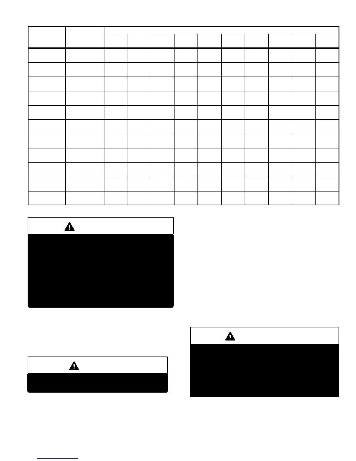
Diameter
−Inches(mm)
10
(3.048)
20
(6.096)
30
(9.144)
40
(12.192)
50
(15.240)
60
(18.288)
70
(21.336)
80
(24.384)
90
(27.432)
100
(30.480)
1/4
(6.35)
.364
(9.246)
43
(1.13)
29
(.82)
24
(.68)
20
(.57)
18
(.51)
16
(.45)
15
(.42)
14
(.40)
13
(.37)
12
(.34)
3/8
(9.53)
.493
(12.522)
95
(2.69)
65
(1.84)
52
(1.47)
45
(1.27)
40
(1.13)
36
(1.02)
33
(.73)
31
(.88)
29
(.82)
27
(.76)
1/2
(12.7)
.622
(17.799)
175
(4.96)
120
(3.40)
97
(2.75)
82
(2.32)
73
(2.07)
66
(1.87)
61
(1.73)
57
(1.61)
53
(1.50)
50
(1.42)
3/4
(19.05)
.824
(20.930)
360
(10.19)
250
(7.08)
200
(5.66)
170
(4.81)
151
(4.28)
138
(3.91)
125
(3.54)
118
(3.34)
110
(3.11)
103
(2.92)
1
(25.4)
1.049
(26.645)
680
(19.25)
465
(13.17)
375
(10.62)
320
(9.06)
285
(8.07)
260
(7.36)
240
(6.80)
220
(6.23)
205
(5.80)
195
(5.52)
1−1/4
(31.75)
1.380
(35.052)
1400
(39.64)
950
(26.90)
770
(21.80)
660
(18.69)
580
(16.42)
530
(15.01)
490
(13.87)
460
(13.03)
430
(12.18)
400
(11.33)
1−1/2
(38.1)
1.610
(40.894)
2100
(59.46)
460
(41.34)
1180
(33.41)
990
(28.03)
900
(25.48)
810
(22.94)
750
(21.24)
690
(19.54)
650
(18.41)
620
(17.56)
2
(50.8)
2.067
(52.502)
3950
(111.85)
2750
(77.87)
2200
(62.30)
1900
(53.80)
1680
(47.57)
1520
(43.04)
1400
(39.64)
1300
(36.81)
1220
(34.55)
1150
(32.56)
2−1/2
(63.5)
2.469
(67.713)
6300
(178.39)
4350
(123.17)
3520
(99.67)
3000
(84.95)
2650
(75.04)
2400
(67.96)
2250
(63.71)
2050
(58.05)
1950
(55.22)
1850
(52.38)
3
(76.2)
3.068
(77.927)
11000
(311.48)
7700
(218.03)
6250
(176.98)
5300
(150.07)
4750
(134.50)
4300
(121.76)
3900
(110.43)
3700
(104.77)
3450
(97.69)
3250
(92.03)
4
(101.6)
4.026
(102.260)
23000
(651.27)
15800
(447.39)
12800
(362.44)
10900
(308.64)
9700
(274.67)
8800
(249.18)
8100
(229.36)
7500
(212.37)
7200
(203.88)
6700
(189.72)
NOTE−Capacity given in cubic feet of gas per hour (kilo liters of gas per hour) and based on 0.60 specific gravity gas.
IMPORTANT
The furnace must be isolated from the gas supply
piping system by closing its individual manual
shut−off valve during any pressure testing of the
gas supply piping system at test pressures equal
to or less than 1/2 psig (3.45 kPa).
The furnace and its individual shut−off valve must
be disconnected from the gas supply piping sys-
tem during any pressure testing of the system at
test pressures greater than 1/2 psig (3.45 kPa). See
figure 44.
When checking piping connections for gas leaks, use pre-
ferred means. Kitchen detergents can cause harmful corro-
sion on various metals used in gas piping. Use of a specialty
Gas Leak Detector is strongly recommended. It is available
through Lennox under part number 31B2001. See Corp.
8411−L10, for further details.
WARNING
Do not use matches, candles, flame or any other
source of ignition to check for gas leaks.
D−Testing Gas Supply Pressure
When testing supply gas pressure, use the 1/8" N.P.T.
plugged tap or pressure post located on the gas valve to fa-
cilitate test gauge connection. See figures 42 and 43.
Check gas line pressure with unit firing at maximum rate.
Low pressure may result in erratic operation or underfire.
High pressure can result in permanent damage to gas valve
or overfire. For natural gas units, operating pressure at unit
gas connection must be between 4.5" W.C. and 13.0" W.C.
For L.P. gas units, operating pressure at unit gas connection
must be between 10.5" and 13.0" W.C.
On multiple unit installations, each unit should be checked
separately, with and without units operating. Supply pres-
sure must fall within range listed in previous paragraph.
E−Check Manifold Pressure
Manifold pressure is the manifold pressure measured when
the gas valve regulator is operating at factory preset level
sensing atmospheric pressure.
IMPORTANT
The White Rodgers 36G gas valve (figure 42) is
equipped with pressure posts for measuring supply
and manifold pressures. The posts provide built−in
hose connections and have an integral 3/32" Allen−
head screw. Rotate the screw counterclockwise one
full turn to permit pressure measurement. Reseat the
screw (rotate one full turn clockwise) after measure-
ments have been taken to prevent gas leakage.
After line pressure has been checked and adjusted, check
manifold pressure. Move pressure gauge to outlet pressure
tap located on unit gas valve (GV1).
Checks of manifold pressure are made as verification of prop-
er regulator adjustment.
 Loading...