Page 33
The condensing unit will be in low speed and the in-
door blower will be operating at a speed equivalent to
the setting of the zone 1 CFM jumper. It may take the
blower 60 to 90 seconds to reach this speed.
3 To check the amount of air being delivered to each
zone, cycle through each zone to confirm that damp-
ers are working correctly and that the amount of air to
each zone is adequate. Keep in mind that the zone
CFM jumpers affect the amount of air delivered in both
cooling and heating modes.
Central Control
1 Press the cooling switch and central switch on the sys-
tem control panel. See figure 28.
The amber LEDs on the cooling switch and the fan
auto switch of the system control panel will be lit.
If heat pump system, Output LED O on (reversing
valve energized).
2 Initiate a cooling demand from master thermostat.
LEDs Y1 and O1 on. (Cool input demand ).
Output LED G on.(Blower on)
LEDs 1DZ through 4DZ off. (All dampers open)
Condensing unit will operate in low speed and out
put LED Y1 and O1 are lit. (compressor on)
Indoor blower will operate at a speed equivalent to
the sum of all zone CFM jumper settings. It may
take the blower 60 to 90 seconds to reach this
speed.
3 Remove all demands.
F−System Off (All Systems)
1− Depress the system off switch on the system control
panel. See figure 28.
The amber LED on the system off switch on the
system control panel will be lit.
2− In this mode, The entire system is shut down and will
not respond to any demands. However, the fan will op-
erate if the fan on switch is selected. It may take the
blower 60 to 90 seconds to reach full speed.
G−Discharge Probe Checkout (All Systems)
It is difficult to checkout the discharge air temperature
probe directly. The temperature of the airstream corre-
sponds to a milliamp signal which passes through the
probe. This signal is not constant and cannot be measured
because the control center samples" the probe once ev-
ery 10 seconds. Each temperature sampling lasts only a
fraction of a second.
The control center is well equipped to monitor the opera-
tion of the probe and determine if a failure has occurred.
The probe should be considered an integral (but replace-
able) part of the control center. The control center will indi-
cate if the probe is operating improperly and needs to be
replaced.
Although it is hard to checkout the probe, it is easy to un-
derstand the purpose of the probe and to observe its op-
eration. Simply observing the probes operation will help
determine if it is operating properly.
The discharge air temperature probe serves several pur-
poses:
1 In cooling systems (and heat pump systems in cooling
mode) the probe varies the speed of the compressor
from high to low to off in order to maintain a constant
discharge air temperature and prevent coil freezing.
See table 5.
2 In gas heating systems, it is responsible for increasing
the speed of the blower to the setting of the CFM jump-
ers after the heat exchanger has warmed up to about
100F.
3 In heat pump systems operating in the heating mode,
the probe varies compressor speed and stages of aux-
iliary heat in order to maintain a constant discharge air
temperature. See table 6.
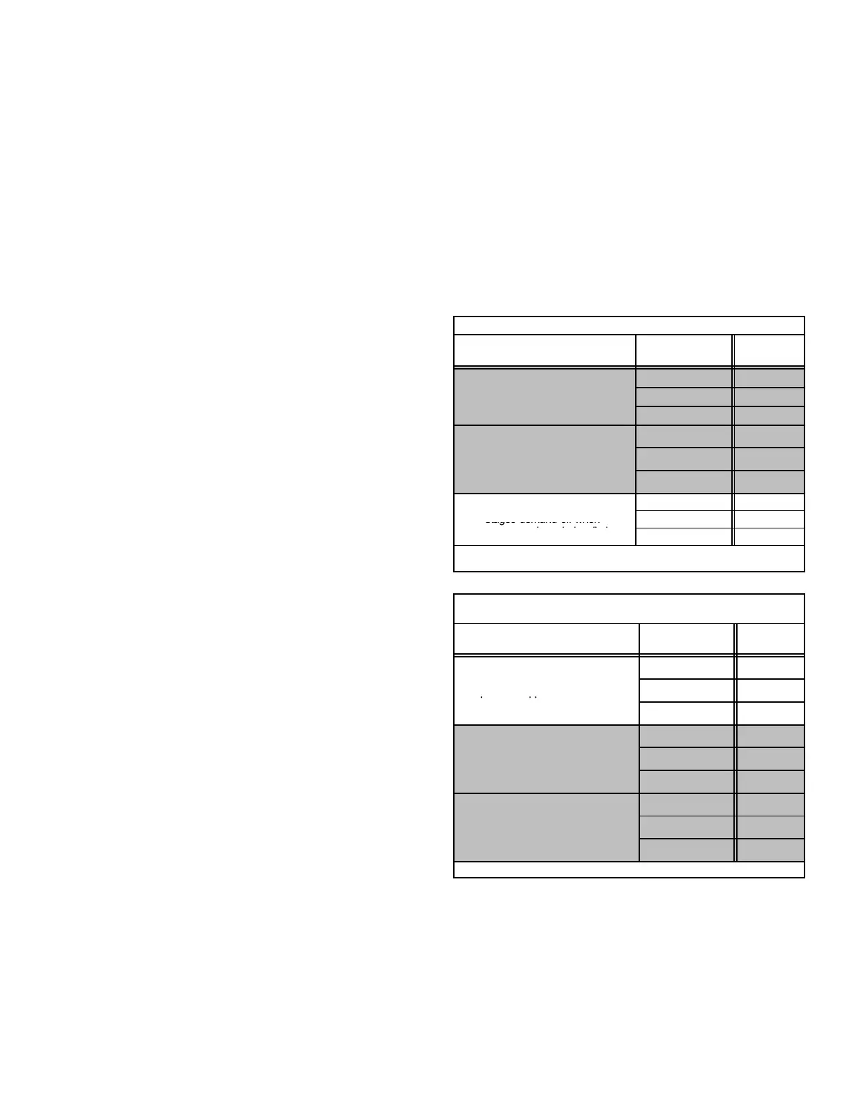
Table 5
Discharge Air Temperature Probe: Cooling Temperatures
Probe Function
response
Discharge Air
Temp." Jumper
Setpoint
Degrees F
High Limit
C+ 70
Shifts compressor to high speed
when temperature rises above
Off 65
w
en
empera
ure r
ses a
ove
limit.
C− 60
Low Limit
Tries to maintain this temperature
C+ 63
Tries to maintain this temperature.
Shifts compressor to low speed
when temperature drops below
Off 58
when temperature drops below
low limit.
C− 53
C+ 45
Stages demand off when
Off 45
temperature drops below limit.
C− 45
Shaded area indicates normal operating range.
Table 6
Discharge Air Temperature Probe: Heating Temperatures
(Heat pump and FM21 systems only)
Probe Function
response
Discharge Air
Temp." Jumper
Setpoint
Degrees F
Safety Limit
Electric Heat: Turns Off Output When
H+ 135
Electric Heat: Turns Off Output When
Temperature Approaches Limit. Heat
Off 130
Pump: Turns Off Output When Tem-
perature Crosses Limit.
H− 125
High Limit
H+ 125
Tries to maintain
this temperature. Shifts compres-
sor to low speed when temperature
Off 120
sor to low speed when temperature
rises above high limit.
H− 115
Low Limit
Electric Heat: turns off output when
H+ 105
Electric Heat: turns o
output when
temperature approaches . Limit. Heat
Pump: turns off output when tem
Off 100
Pump: turns off output when tem-
perature crosses limit.
H− 95
Shaded area indicates normal operating range.
 Loading...

