Page 29
9-Burner Controls A3
A3 controls gas heat section burner controls. Burner con
trols are factory set and are not adjustable. The control
makes three attempts at ignition and then locks out the sys
tem if ignition is not obtained after the third trial. Reset after
lockout requires only breaking and remaking thermostat
demand. The control shuts off gas flow immediately in the
event of a gas or power failure. Upon restoration of gas
and power, the control will restart the ignition sequence
and continue until flame is established or system locks
out. For a more detailed description see the Gas Heat
Components section.
10-Power Exhaust Relay K65 (PED units)
Power exhaust relay K65 is a N.O. DPDT relay with a
24VAC coil. K65 is used in all LGH units equipped with the
optional power exhaust dampers. K65 is energized by the
economizer control panel (A56), after the economizer
dampers reach 50% open (adjustable in ECTO). When K65
closes, the exhaust fans B10 and B11 are energized.
11-Blower Motor Overload Relay S42
Two hp high efficiency blower motors and M-volt unit blower
motors are equipped with an overload relay. High efficiency
blower motors and M-volt unit blower motors manufactured
before Dec. 19, 2010, are equipped with the relay. Ultra
high efficiency units equipped with a direct drive blower
have an internal overload.
The relay (S42) is connected in line with the blower motor to
monitor the current flow to the motor. When the relay sens
es an overload condition, a set of normally closed contacts
open to de-energize the blower. Units will be equipped with
a relay manufactured by Telemecanique figure 9 or
Siemens figure 10.
12-Unit Controller A55
The Unit Controller provides all unit control functions, unit
status information, unit diagnostics, programmable pa
rameters and USB verification and profile sharing. Use the
Unit Controller keypad and display to navigate through
menus. Software is also available to access the Unit Con
troller. Refer to the Unit Controller guide provided with the
unit. Thermostat wires are connected to J297 on the Unit
Controller.
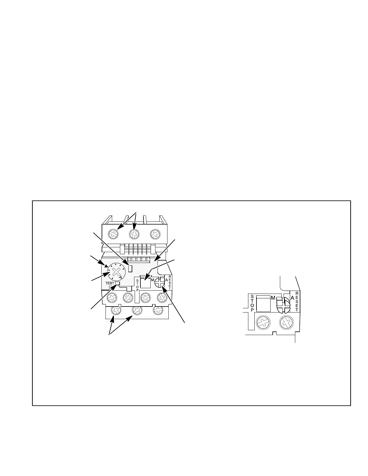
CLEAR
COVER
(SHOWN
CLOSED)
STOP
BUTTON
(RED)
RED TEST
BUTTON
(Push To Test)
AMP SETTING
CONTROL
(BLUE DIAL)
TRIP
INDICATION
WINDOW
LINE VOLTAGE IN
AMP SETTING
POINTER
BLUE RESET SCREW
(Shown in AUTO position as
shipped from the factory)
LOAD VOLTAGE OUT
DETAIL SHOWING RESET BUTTON
ADJUSTED TO MANUAL POSITION
Lift clear cover and turn adjustment screw
counterclockwise. Reset screw will pop out
when pointer is in M (manual position). Close
cover to lock reset screw into position.
TELEMECANIQUE OVERLOAD RELAY
Lift clear cover to adjust relay amp setting according to value given on the blower motor nameplate.
Proper relay amp setting equals motor nameplate FLA X service factor of 1.15 X .95.
Cover must also be lifted to adjust control mode from automatic reset to manual reset (see detail
above) and to test the control.
Control must be in the manual reset mode to perform a test. Use a pointed object to press the small
red test button. A yellow marker should appear in the trip indication window to the right of the amp
setting control. Press the blue reset screw to reset the relay.
The red STOP button opens the normally closed contacts which power the blower motor. This button
stops blower motor operation as long as it is pressed in.
FIGURE 9
 Loading...