Page 42
D-GAS HEAT COMPONENTS
See unit nameplate for all -1 model unit Btuh capacities.
See SPECIFICATIONS tables or unit nameplate for
Btuh capacities in -2 model units. Flexible pipe will feed
supply gas to both sections. If for service the flexible
connection must broken, hand tighten then turn addi
tional 1/4” with a wrench for metal to metal seal (do not
overtighten).
NOTE - Do not use thread sealing compound on flex pipe
flare connections.
1-Control Box Components A3, A55, T3, K13
WARNING
Shock hazard. Spark related compo
nents contain high voltage which can
cause personal injury or death. Discon
nect power before servicing. Control is
not field repairable. Unsafe operation
will result. If control is inoperable, sim
ply replace the entire control.
Burner Ignition Control A3
The ignition control is located in the heat section and is manu
factured by Johnson Controls. See table 3 for LED codes.
TABLE 3
Manufacturer LED Code Description
Johnson
Steady “ON” Normal
.5 sec on / 2.5 sec off Reset Mode
“OFF” No Power or Detected Failure
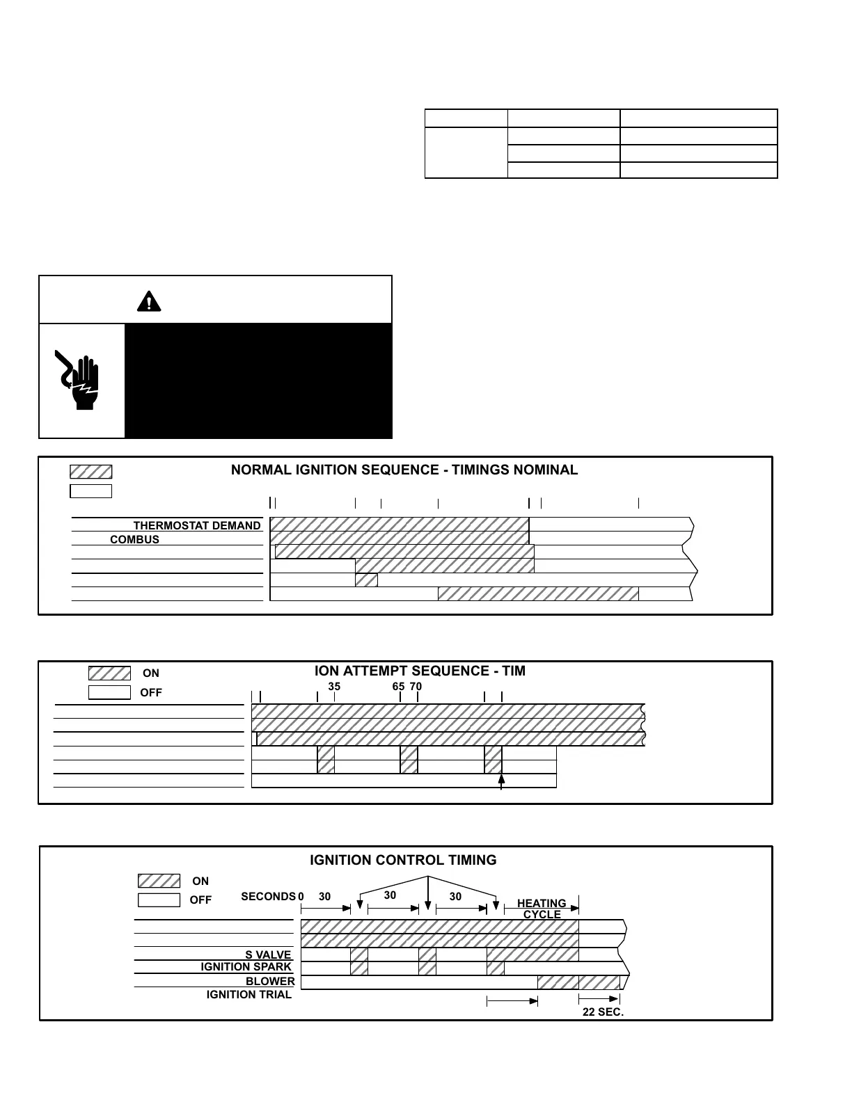
The ignition control provides three main functions: gas
valve control, ignition and flame sensing. The unit will usu
ally ignite on the first attempt; however, the ignition attempt
sequence provides three trials for ignition before locking
out. The lockout time for the Johnson control is 5 minutes.
After lockout, the ignition control automatically resets and
provides three more attempts at ignition. Manual reset after
lockout requires breaking and remaking power to the igni
tion control. See figure 22 for a normal ignition sequence
and figure 23 for the ignition attempt sequence with retrials
(nominal timings given for simplicity). Specific timings for
the ignition controls are shown in figure 24.
ÉÉÉÉÉÉÉÉÉÉÉÉÉ
ÉÉÉÉÉÉÉÉÉÉÉÉÉ
NORMAL IGNITION SEQUENCE - TIMINGS NOMINAL
THERMOSTAT DEMAND
COMBUSTION AIR BLOWER
GAS VALVE
IGNITION SPARK
BLOWER
IGNITION TRIAL
SECONDS 0 30 35 0 110
ON / CLOSED
OFF / OPEN
END OF
DEMAND
1
ÉÉÉÉÉÉÉÉÉÉÉÉÉ
ÉÉÉÉÉÉÉÉÉÉÉÉÉ
COMBUSTION AIR PROVE SWITCH
5 570
FIGURE 22
FIGURE 23
RETRIALS - IGNITION ATTEMPT SEQUENCE - TIMINGS NOMINAL
THERMOSTAT DEMAND
COMBUSTION AIR BLOWER
GAS VALVE
IGNITION SPARK
BLOWER
IGNITION TRIAL
SECONDS 0 30 35 70
ON
OFF
ÉÉÉÉÉÉÉÉÉÉÉÉÉÉÉÉÉÉÉÉ
ÉÉÉÉÉÉÉÉÉÉÉÉÉÉÉÉÉÉÉÉ
ÉÉÉÉÉÉÉÉÉÉÉÉÉÉÉÉÉÉÉÉ
ÉÉÉÉÉÉÉÉÉÉÉÉÉÉÉÉÉÉÉÉ
65 100 105
WATCHGUARD
LOCKOUT
COMBUSTION AIR PROVE SWITCH
5
FIGURE 24
ÉÉÉÉÉÉÉÉÉÉÉÉÉÉ
ÉÉÉÉÉÉÉÉÉÉÉÉÉÉ
THERMOSTAT DEMAND
COMBUSTION AIR BLOWER
GAS VALVE
IGNITION SPARK
BLOWER
IGNITION TRIAL
SECONDS 0 30
ON
OFF
IGNITION CONTROL TIMING
30
30
HEATING
CYCLE
6 (+3.4, -2.0) SEC.
END OF
THERMOSTAT
DEMAND
123
42 SEC. 122 SEC.
 Loading...