Page 38
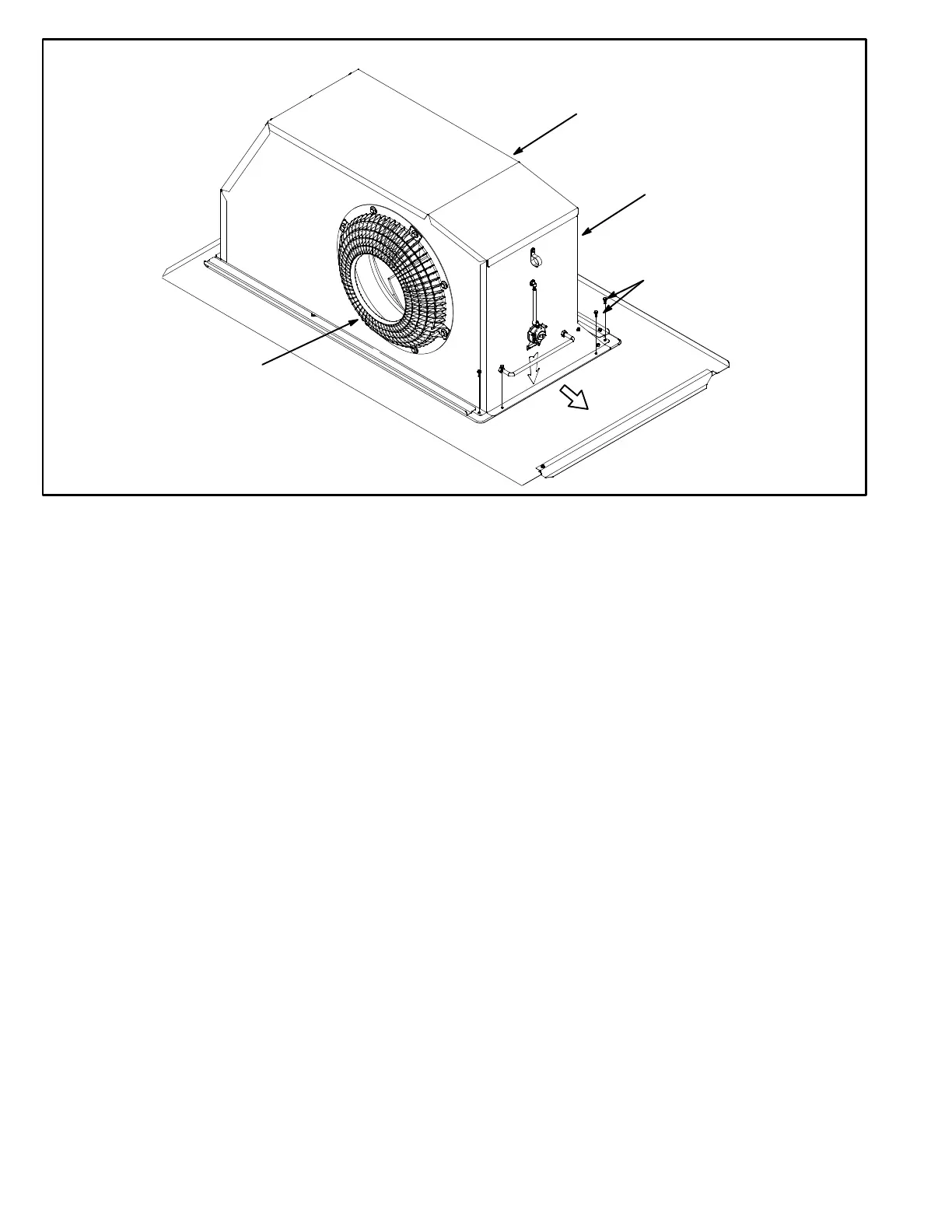
DIRECT DRIVE BLOWER ASSEMBLY
INLET
GRID
REMOVE TWO SCREWS
ON EACH SIDE TO SLIDE
BLOWER OUT OF UNIT
BLOWER
HOUSING
BLOWER MOTOR
SECURED TO THIS
SIDE OF HOUSING
FIGURE 18
C-Blower Compartment
The blower compartment is located between the evapora
tor coil and the condenser coil section. The blower assem
bly is secured to a sliding frame which allows the blower
motor assembly to be pulled out of the unit. See figure 16.
17, or 18.
Belt Drive Blowers
1- Loosen the reusable wire tie which secures the blower
wiring to the blower motor mounting plate.
2- Remove and retain screws on either side of sliding
frame. Pull frame toward outside of unit.
3- Slide frame back into original position when finished
servicing. Reattach the blower wiring in the previous lo
cation on the blower motor base using the wire tie.
4- Replace retained screws on either side of the sliding
frame.
Direct Drive Blowers
1- Loosen the reusable wire tie which secures the con
trols and high voltage blower wiring to the blower hous
ing.
2- Remove and retain screws in front and on either side
of blower housing. Pull frame toward outside of unit.
3- Slide frame back into original position when finished
servicing. Reattach the blower wiring in the previous lo
cation on the blower housing using the wire tie.
4- Replace retained screws in front and on either side of
the blower housing.
1-Blower Wheels
Belt drive blowers are equipped with one 15 in. x 15 in. (381
mm x 381 mm) blower wheel. Ultra high efficiency units
may be equipped with an optional direct drive blower as
sembly with a backward inclined blower wheel.
2-Indoor Blower Motor B3
Belt driven blowers use three‐phase single‐speed blower
motors. CFM adjustments are made by adjusting the motor
pulley (sheave). Ultra high efficiency units may be
equipped with an optional direct drive blower assembly with
a three-phase, variable speed, direct drive blower motor.
All motor specifications are listed in the SPECIFICA
TIONS (table of contents) in the front of this manual. Units
may be equipped with motors manufactured by various
manufacturers, therefore electrical FLA and LRA specifi
cations will vary. See unit rating plate for information spe
cific to your unit.
OPERATION / ADJUSTMENT
VFD / Direct Drive Units - The blower rotation will always
be correct on VFD units. Checking blower rotation is not a
valid method of determining voltage phasing for incoming
power. To check for proper voltage phasing, measure com
pressor suction and discharge pressures. Make sure suc
tion pressure decreases and discharge pressure increases
on start-up.
VFD / Direct Drive Units and Units Equipped With Op
tional Factory-Installed Voltage or Phase Detection -
The Unit Controller checks the incoming power during
start-up (A55 P299-1 and P269-2). If the voltage, phase,
or frequency is incorrect, the Unit Controller will display an
alarm and the unit will not start. If line voltage is corrected,
 Loading...