4
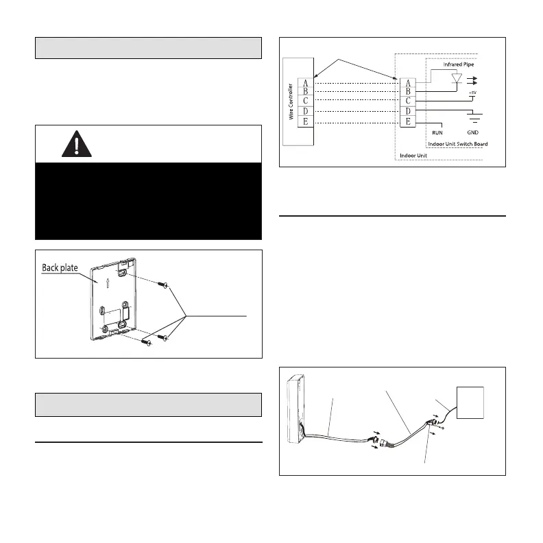
Installing Back Plate on Drywall
When installing the back plate to a at drywall
surface, use the provided screws for securing
back plate to drywall (M4x20). Also use provided
wall anchors if required.
IMPORTANT
Always install back plate on at
surface. Do not distort back plate
by over-tightening the mounting
screws.
Figure 3. Securing Back Plate to Drywall
Making Connections
Wiring Diagram
Refer to the following to illustrations on connecting
the provided cables to the wired controller and
indoor unit.
5-pin shielded cable
5-pin
connectors
Figure 4. Wiring Diagram
Cable Connection Illustration
1. Connect the 5-pin shielded cable assem-
bly to connection on the wired controller.
2. Connect the 5-pin shielded cable assem-
bly to the 5-pin shielded extension cable.
3. Connect the 5-pin shielded extension ca-
ble to the indoor unit display cable con-
nection.
NOTE: Use the provided M4x8 screw
with washer to secure the ground
connector.
Ground Connector
indoor
unit
Wire controller
5-pin shielded
cable assembly
5-pin shielded
extension
cable assembly
Indoor unit
display cable
connection
Figure 5. Cable Assembly Connections

 Loading...