10
Indoor Unit Installation
CAUTION
In order to avoid injury, take proper precaution when
lifting heavy objects.
Unit Placement Considerations
AVOID
Do not install the unit in the following locations:
• Areas exposed to petrochemicals or petrochemical
products
• Areas exposed to salt or other corrosive materials or
caustic gases
• Areas exposed to extreme voltage variations (such as
factories
• Tightly enclosed areas that may impede service of the
unit
• Areas exposed to fossil fuels (such as oil or gas in
kitchens)
• Areas exposed to strong electromagnetic forces
• Areas exposed to acids or alkaline detergents
DO
• Place the unit so that it is not exposed to direct sunlight
• Ensure the structural ceiling can support the weight of
the unit
• Select a location where condensate line will have the
shortest run to a suitable drain per local codes.
• Allow sufcient space around unit for proper operation
and maintenance
• Install unit a minimum of 3 feet (1m) away from any
antenna, power cord (line) radio, telephone, security
system, or intercom. Electrical interference and radio
frequencies from any of these sources may affect op-
eration
• Be sure to instruct customers how to properly operate
the unit (especially maintenance of air lter, and oper-
ation procedure) by having them carry out operations
themselves while looking at the manual provided with
the controller
Floor Installation
• Locate a suitable position within the space where
maintenance access and supply air will not be restrict-
ed or affected by obstacles. See “Figure 10. Indoor
Unit Clearances - Inches (mm)” on page 9 for min-
imum clearances
• Place the MCFA or MCFB on a wall which is both ca-
pable of supporting the unit’s weight and which is con-
structed to enable the unit to t ush on the wall. An
uneven wall may lead to vibration and subsequent unit
damage
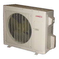
Electrical
Connections
Refrigerant / Drain
Pipe Connections
Figure 11.
Units are wall mounted using hanging
brackets.
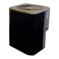
1. Remove the side panels and grille to expose factory-
installed hanging brackets on the sides of the unit.
Side Panel
Grille
Side Panel
Factory Installed
Hanging Brackets
Figure 12. Remove Side Panel and Grille
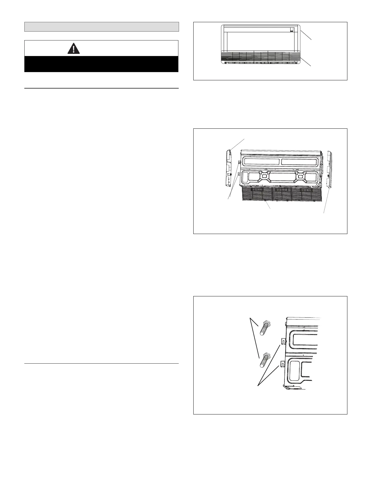
2. Install four mounting bolts (appropriate for your
application) to the wall. See “Figure 8. MCFA and
MCFB Indoor Unit Dimensions - Inches (mm)” on
page 8 to ensure proper positioning of the bolts.
3. Upon conrming the four bolts are level, correctly
spaced and secured to the wall; lift the unit onto the
brackets. Conrm the unit is level before continuing.
Factory Installed
Hanging Brackets
Field-Installed
Mounting Bolts
Figure 13. Hang Unit on Mounting Bolts
 Loading...