26
P5
CN24
CN25
CN17
CN8
CN18
HEAT_Y
SV
4-WAY
BLUE
CN4
CN2
CN3
CN1
COMP
U
V
W
CN6
CN9
10
CN2
U
V
W
BLUE
BLACK
RED
RED
BLACK
CT1
DCFAN2
DCFAN1
6
3
P6
CN3
Outdoor main Controller
BLUE
Y/G
Y/G
COMP TOP
OLP TEMP
SENSOR
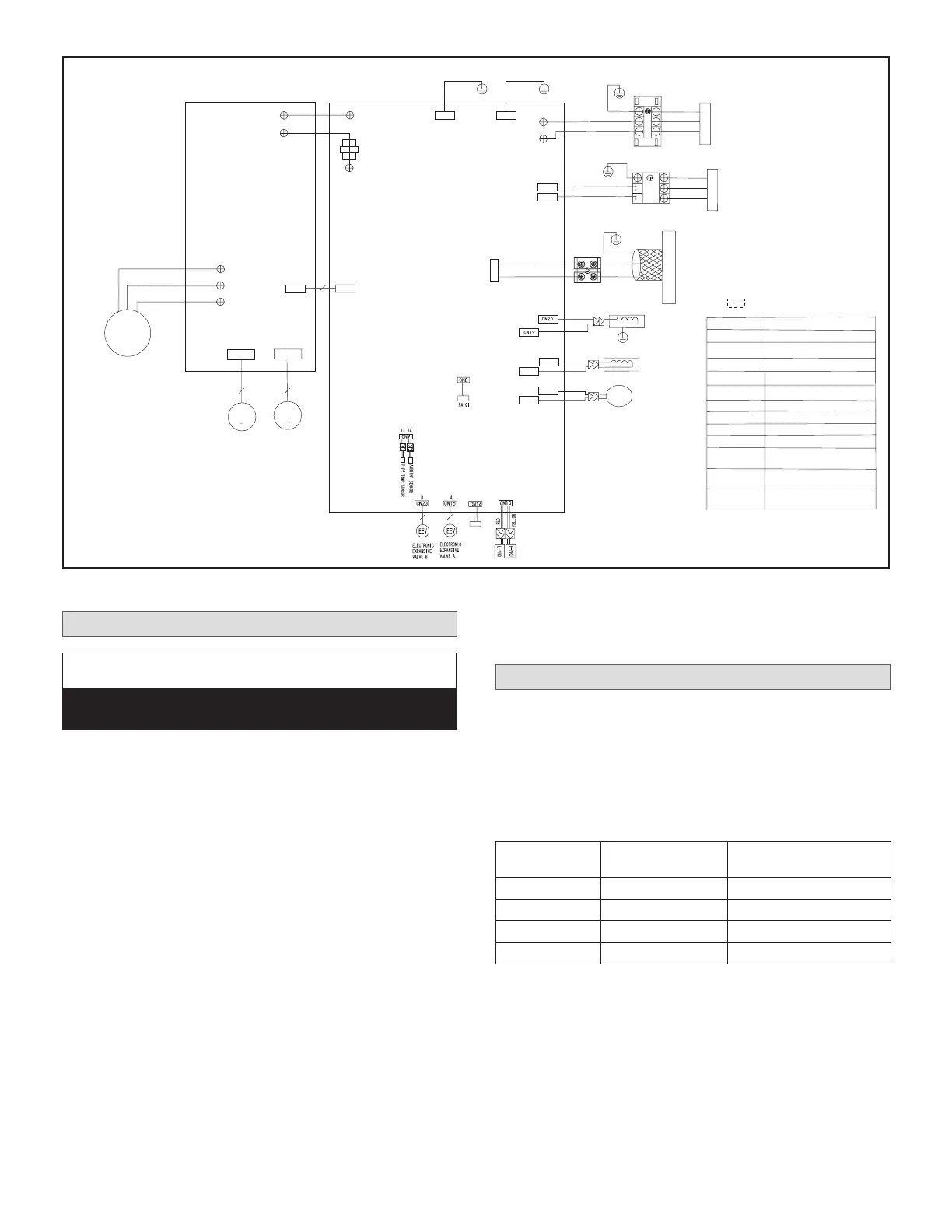
Notes:
CN5
CODE
PART NAME
COMP
CAP1,CAP2
COMPRESSOR
FAN MOTOR CAPACITOR
EEV
DCFAN1,DCFAN2
OUTDOOR DC FAN
HEAT_D,HEAT_Y
H-PRO
CRANKCASE HEATING
HIGH PRESSURE SWITCH
L-PRO
4-WAY
PAIQI
T3
T4
LOW PRESSURE SWITCH
4-WAY VA LVE
EXHAUST TEMPERATURE
SENSOR
CONDENSER TEMPERATURE
SENSOR
OUTDOOR AMBIENT
TEMPERATURE SENSOR
AC CURRENT DETECTOR
ELECTRIC EXPANSIVE VALVE
CT1
IPM&PFC BOARD
This symbol indicates the element is optional,
the actual shape shall be prevail.
HEAT_D
BLACK
RED
TO INDOOR UNIT
(1)L1
Y/G
XT2
(2)L2
P7
P8
BROWN
BLUE
TO INDOOR COMM. BUS
YELLOW
GRAY
S1
S2
NOTE:Please use 2-core
shielded wire.
XT3
CN22
P
Q
Y/G
L2
L1
XT1
Y/G
POWER SUPPLY
RED
BLACK
6
3
RED
BLACK
WHITE
The electric heating
belt of chassis
The electric heating
belt of compressor
RED
BLACK
RED
Figure 44. 208/230V MLB036S4S-*P and MLB048S4S-*P Outdoor Unit Wiring Diagram
Unit Start-Up
IMPORTANT
Units should be energized 24 hours before unit start-up
to prevent compressor damage as a result of slugging.
1. Inspect all factory- and eld-installed wiring for loose
connections.
2. Verify that the manifold gauge set is connected.
3. Add additional refrigerant charge if required before
opening valves and while system is still under a
vacuum.
4. Open the liquid and gas line service valves to release
the refrigerant charge contained in outdoor unit into
the system.
5. Replace the stem caps and tighten to the value listed
in “Table 4. Flare Nut Torque Recommendations” on
page 16.
6. Check voltage supply at the outdoor unit terminal strip.
The voltage must be within the range listed on the
unit’s nameplate. If not, do not start the equipment
until you have consulted with the power company and
the voltage condition has been corrected.
7. Refer to the included user guide to operate the system
using the provided remote control.
8. Visually check for binding of both indoor and outdoor
fans.
Adding Refrigerant for Longer Line Set
The outdoor unit is factory-charged with refrigerant.
Calculate the additional refrigerant required according to
the diameter and the length of the liquid pipe between the
outdoor unit and indoor unit connections.
Be sure to add the proper amount of additional refrigerant.
Failure to do so may result in reduced performance.
Table 8. Additional Refrigerant Charge
Pipe Length
Amount of Refrigerant
to add
18 >25 (7.5) 0.161 oz/ft (15g/m)
24 >25 (7.5) 0.322 oz/ft (30g/m)
36 >25 (7.5) 0.322 oz/ft (30g/m)
48 >25 (7.5) 0.322 oz/ft (30g/m)
 Loading...