 Loading...
Do you have a question about the Lenze 2131 and is the answer not in the manual?
| Brand | Lenze |
|---|---|
| Model | 2131 |
| Category | Control Unit |
| Language | English |
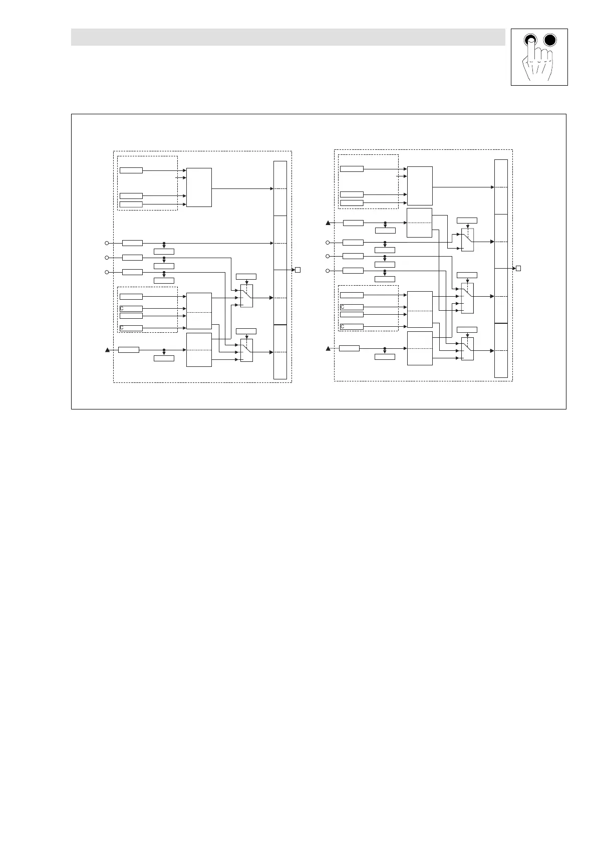
Overview of connection diagrams for the 2131 module with controllers.
Shows connection diagrams of the 2131 module with different controllers.
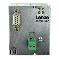
Details the pinout and function of the 9-pole SubD connector.
Instructions for physically mounting the fieldbus module onto the controller.
General notes on electrical installation and potential interference.
Explains how to supply the fieldbus module with 24 V DC voltage.
Provides warnings and guidelines for wiring the module to a host system with isolation.
Details wiring features, PROFIBUS wiring, and warnings for bus systems.
Details host system configuration using Siemens COM-ET200 software.
Steps to commission the module, including LED status and station address.
Configures drive control using PROFIBUS for 93XX controllers.
Steps to enable the controller after PROFIBUS configuration.
Explains the two parameter types: Lenze and DRIVECOM parameters.
Details Lenze parameter data types and value ranges.
Explains DRIVECOM parameters, their indexing, and data types.
Details address setting methods and Lenze default settings.
Describes selectable user data lengths for PROFIBUS-DP.
How the channel enables parameter setting and diagnostics.
Further details on subindex, index calculation, and data/error fields.
How to perform read and write jobs for parameter communication.
Explains process data memory for fast transmission and types: PO and PI data.