3 System Description
EDBC250SBC |1.1
l
ll
l
11
3 System Description
3.1 General conditions of use
This section describes the general characteristics of Safety modules which are important for
the installation, wiring and troubleshooting.
You can find an overview of the system properties in section 5.1.1 System features on page 21.
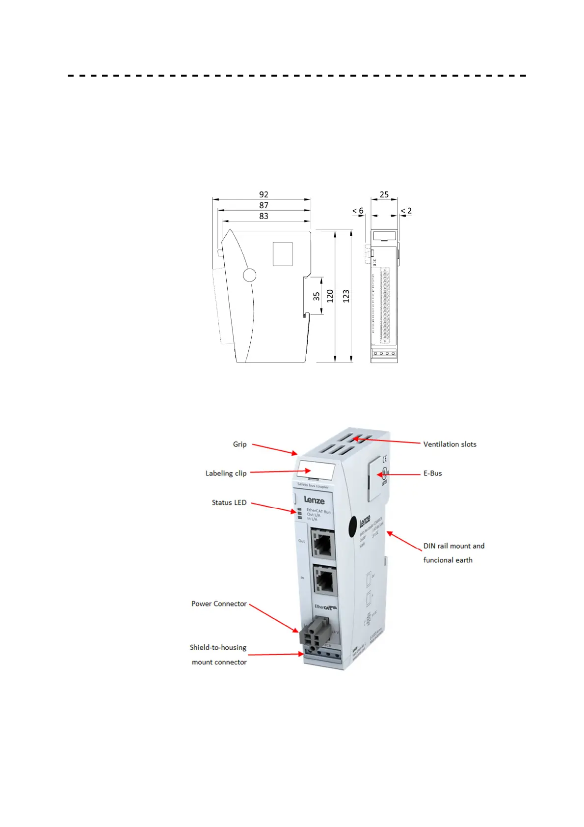
3.2 Dimensions
3.3 Mechanical Design
The Safety bus coupler and the Safety I/O-modules differ in their connectors and indicators,
however.
Figure 2 Module layout
The housing mount consists of an aluminum profile with an integral snap-on device used to
snap the module to a 35mm DIN rail. The housing trough including the optical fibers for the
status indicators, the side face and the front is made of plastic and contains the module. The
optical fibers for the signal state indicators (LEDs) are located next to the spring-assisted combi
plug. They slightly protrude from the housing and allow a clear diagnosis at a glance.
 Loading...