3 System Description
EDBC250SBC |1.1
l
ll
l
17
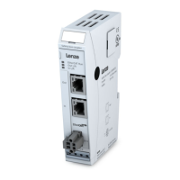
3.4.2 Safety Bus coupler
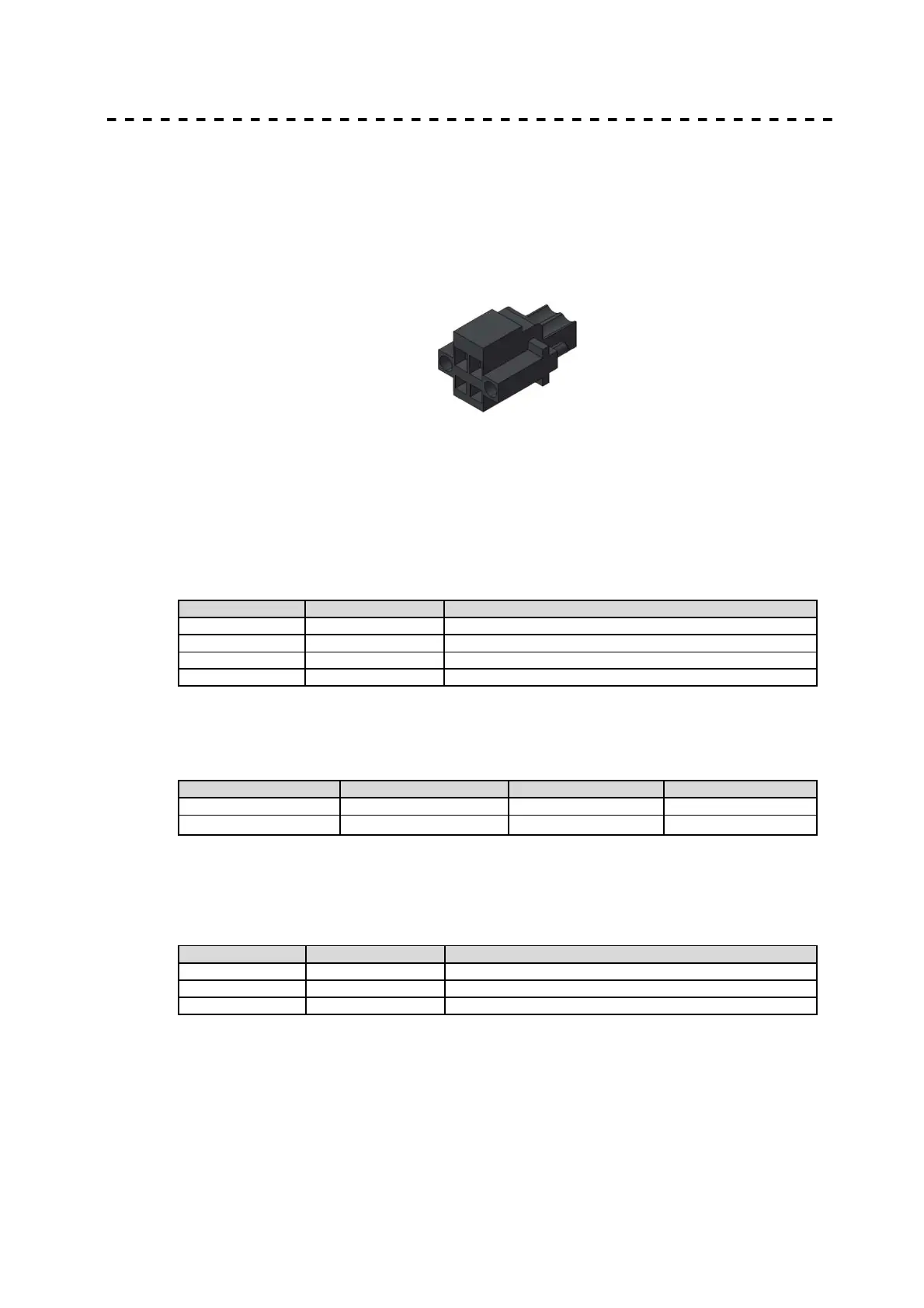
A 2-pin plug-in terminal block with screw flange is used to connect the system supply to the
bus coupler. Since the bus coupler supplies power to both the E-bus and the logic circuits of
the Safety controller c250-S and the Safety I/O-modules, its power consumption depends on
the Safety controller c250-S and the number of Safety I/O-modules connected.
Power to the I/O module outputs is supplied separately
Figrue 6: Spring-assisted terminal block with screw flange for the Bus coupler
3.5 Statusanzeigen
3.5.1 LED "EtherCAT Run"
An LED labeled "EtherCAT Run" is located on both the bus coupler and the I/O modules. It
indicates the state of the EtherCAT ASIC.
unrestricted data exchange
Due to the specification "ETG.1300 Indicator and Labeling" successively following changes in
name and flashing were performed from October 2012.
In, Out In L/A, Out L/A no change
3.5.2 LED "In L/A", LED "Out L/A"
The "In L/A" and "Out L/A" LEDs are located on the bus coupler. They indicate the physical
state of the Ethernets (Link/Activity).
 Loading...