3 System Description
EDBC250SBC |1.1
l
ll
l
13
3.3.2 Installation
The modules of the Lenze Safety System are intended for mounting rail installation (DIN EN
50022, 35 x 7.5 mm).
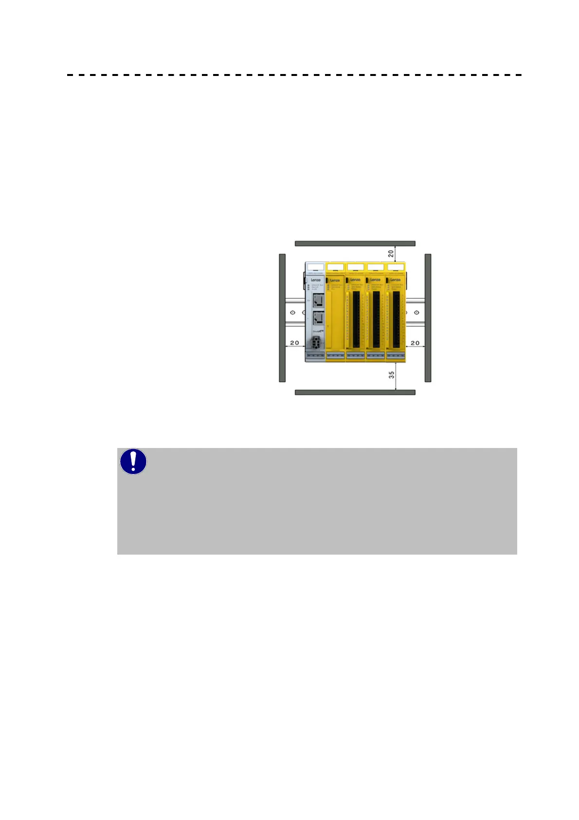
Installation position
The mounting rail is placed horizontally and the female connector strip of the modules face
forward. For a sufficient ventilation of the convection slits the minimum distance must not fall
below 20mm upward and 35mm to adjacent equipment and control cabinets The lateral
distance to external devices and cabinet controls must not fall below 20mm.
Figure 3: Installation position
Installation order in the Lenze Safety System
NOTE
To ensure smooth function of the entire Lenze Safety System, the Safety
modules must be arranged based on their e-bus load. The modules with the
biggest e-bus load are to be arranged directly next to the head modules (bus
coupler or controller). Make sure that you note the maximum bus load of the
head module.
Safety I/O-modules shall be arranged directly next to the head module.
 Loading...