Installation
Electrical installation
Connection for the CAN bus
5
l
24
EDSMF2181IB EN 3.0
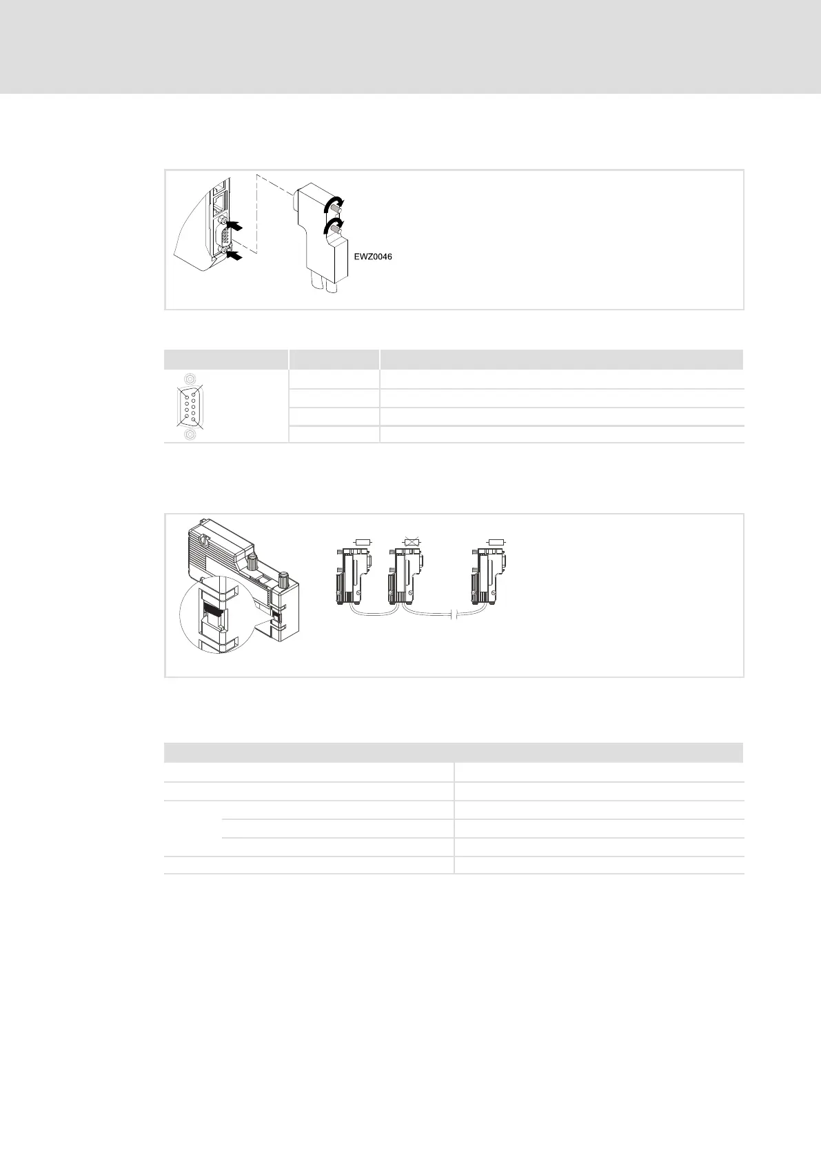
5.2.5 Connection for the CAN bus
2181FEW001K
Assignment of the Sub−D plug connector
View Pin Assignment
1
6
5
9
1, 4, 5, 6, 8, 9 −
2 CAN−LO
3 CAN−GND
7 CAN−HI
Between CAN_LOW and CAN−HIGH the CAN bus has to be terminated by resistors (120W).
The Sub−D plug with an integrated terminating resistor (order no. EWZ0046, not included
in the scope of supply) complies with the recommendation DS 102−1 of CiA.
L
E
W
Z0046
O
F
F
O
N
ON
O
FF
ð
ð
ð
ð
OUTIN IN IN
On
Off
On
120 120
120
L
EWZ0046
L
EWZ0046
L
EWZ0046
2181FEW004
Specification of the transmission cable
We recommend the use of CAN cables in accordance with ISO 11898−2:
CAN cable in accordance with ISO 11898−2
Cable type Paired with shielding
Impedance 120 W (95 ... 140 W)
Cable resistance/cross−section
Cable length £ 300 m £ 70 mW/m / 0.25 0.34 mm
2
(AWG22)
Cable length 301 1000 m £ 40 mW/m / 0.5 mm
2
(AWG20)
Signal propagation delay £ 5 ns/m
 Loading...


