Commissioning
Setting the node address
7
EDK2191DB DE/EN/FR 2.0
37
H2_Teilnehmeradresse_einstellen−TN−Adresse
Setting the node address
Note!
ƒ Use different node addresses for several networked inverters.
The Lenze setting for the node address (node ID) has the value ’4’:
– link switch in position ’0’
– right switch in position ’4’
ƒ Switch the voltage supply of the inverter/communication module off and
on again to activate changed settings.
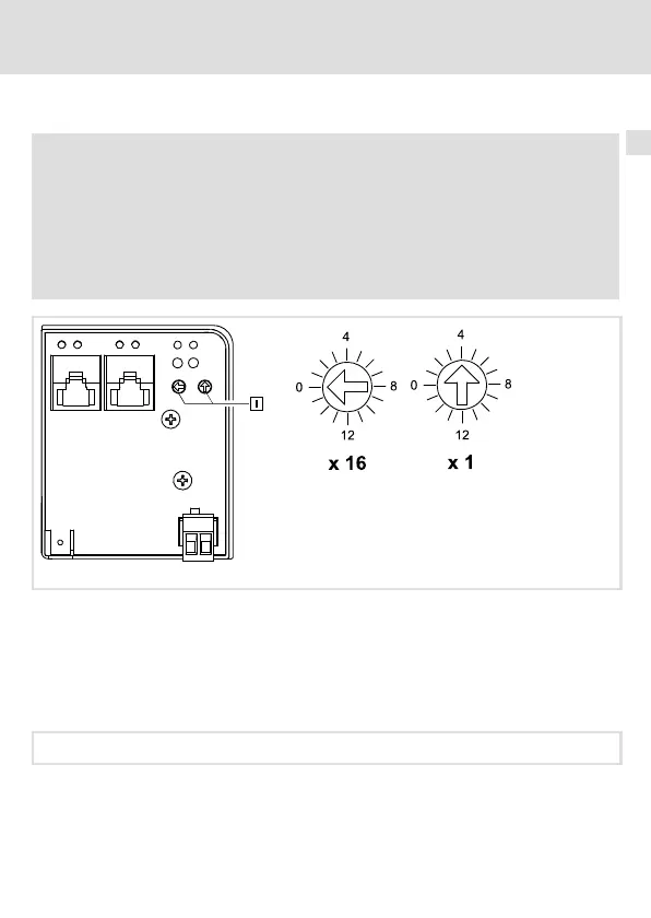
2191EPL001B
Fig. 2 Setting the node address
Each node has to be assigned to a unique address (node ID).
ƒ Valid address range for slave (controlled node): 1 ... 239
ƒ The corresponding IP address of the communication module results from the setting
of the two rotary switches.
IP address: 192.168.100.<Node ID>
(Value
NJ
LeftSwitch
Nj
16))(Value
NJ
RightSwitch
Nj
) + NodeAddress
 Loading...


