Commissioning
Initial switch−on
6
37
EDSMF2191IB EN 2.0
6.4 Initial switch−on
Switch on the inverter and check whether it is ready for operation using the diagnostic
LEDs at the front of the communication module.
ƒ Red diagnostic LEDs must not be on.
ƒ The following signalling should be visible:
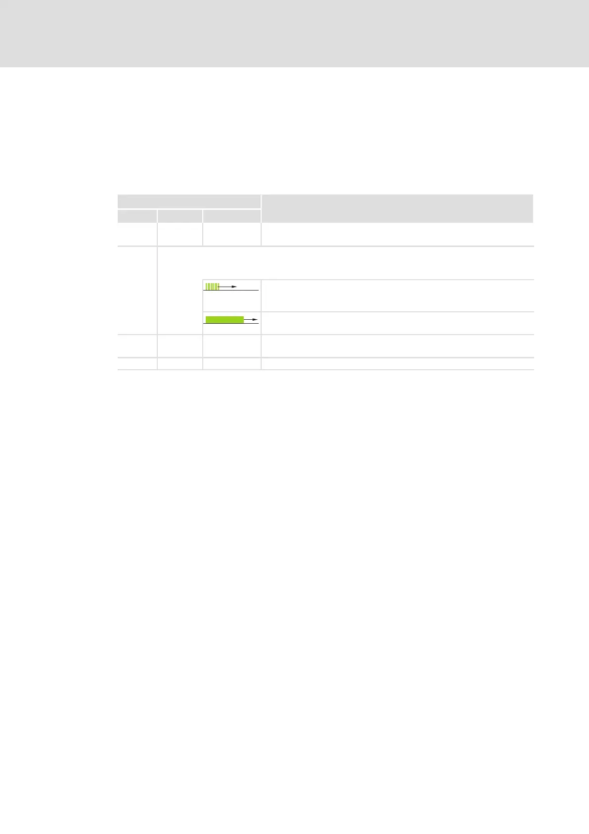
LED
Description
Pos. Colour Condition
green on The communication module is supplied with voltage and is connected to
the standard device.
green
The NMT state machine triggers the two−colored LED:
l Green: Display of status messages
l Red: Display of error messages
NMT_CS_BASIC_ETHERNET
(LED is blinking with a frequency of 10 Hz or depending on the
connection state)
NMT_CS_OPERATIONAL / NMT_MS_OPERATIONAL
(LED is lit permanently.)
green blinking Depending on the connection state, the data is transmitted or received
(ACTIVITY).
yellow on Ethernet connection is available (LINK).

 Loading...


