Installation électrique
Affectation des bornes de raccordement
4
109
EDBPM−H505 DE/EN/FR 6.1
4 Installation électrique
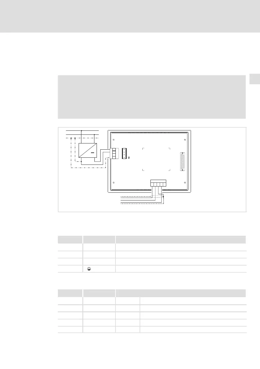
4.1 Affectation des bornes de raccordement
Stop !
ƒ Risque d’endommagement des appareils connectés. Relier
impérativement le conducteur PE conformément à l’illustration !
ƒ Ne procéder au câblage de l’unité de commande qu’en l’absence
de tension !
INPUT VOLTAGE: 18-32 VDC 10 W
FUSE 800 mA
+24 VDC
0 VDC
1
2
3
4
N. C.
MSP
N.C.
CAN+
Shield
CAN-
V-
12345
CAN-GND
CAN-LO
CAN-HI
~
PE
N
L1
+18…32VDC
1234
h505_001
Fig.4−1 Affectation des bornes
Alimentation CC
Borne Désignation Explication
1 DC +24 V Tension d’alimentation (+18 V ... 32 V CC)
2 DC 0 V GND tension d’alimentation, potentiel de référence
3 N.C. Non connecté
4 Potentiel PE
Bus Système CAN
Borne Désignation Explication
1V− GND Potentiel de référence
2 CAN− LO Bus Système LOW (BAS) (ligne de données)
3 Shield Raccorder le blindage du câble Bus Système.
4 CAN+ HI Bus Système HIGH (HAUT) (ligne de données)
5 N.C. Non connecté
 Loading...