ENGLISH
9
Installation
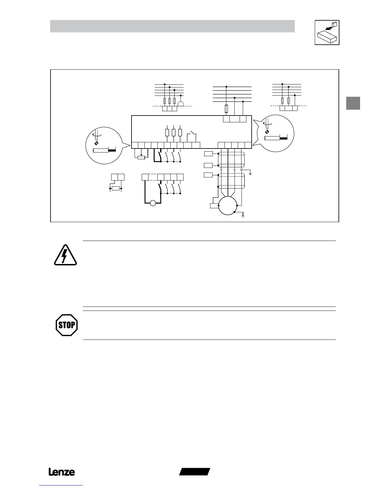
3.2.3 Connection diagram
6 mm / 0 24 n
0 2 Nm / 2 lb in
< 1 mm² / AWG 26 16
0 5 Nm / 4 5 lb n
6 mm / 0 24 in
1/N/PE 180 V 0 % 264 V + 0 %
48 Hz 62 Hz
2/PE 180V 0% 264V + 0 %
48 Hz 62 Hz
3/PE 180V 0% 264V + 0 %
48 Hz 62 Hz
PE
N
L3
L2
L1
PE
N
L3
L2
L1
PE
N
L3
L2
L1
PE
PE
U
V W
PE
L1
L2/N
smd
+10V
+12V
COM
AIN
L1
L2
L3
PE
PE
PE
M
3~
8
9
20
28
E1
E2
E3
K14
K12
7
PES
PES
PES
PES
7 28
E1E2
E3
87
250
0 ... 20 mA
4 ... 20 mA
+12 VDC 0 %
+30 VDC + 0 %
+
_
PE
L1
L2/N
1k … 10k
DANGER!
• Hazard of electrical shock! Circuit potentials are up to 240 VAC above earth ground.
Capacitors retain charge after power is removed. Disconnect power and wait until the
voltage between B+ and B- is 0 VDC before servicing the drive.
• Do not connect mains power to the output terminals (U,V,W)! Severe damage to the
drive will result.
• Do not cycle mains power more than once every three minutes. Damage to the drive
will result.
STOP!
If the kVA rating of the AC supply transformer is greater than 10 times the input kVA rating of the drive(s),
an isolation transformer or 2-3% input line reactor must be added to the line side of the drive(s).
smd003
 Loading...