ENGLISH
10
Installation
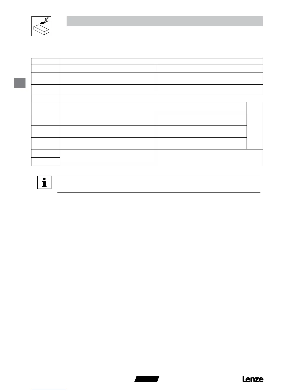
3.2.4 Control terminals
Note
LOW = 0 to +3V, HIGH = +12 to +30V.
Protection against contact
• All terminals have basic isolation (single insulating distance)
• Protection against contact can only be ensured by additional measures i.e. double insulation-
Terminal
Data for control connections (printed in bold = Lenze setting)
7
Reference potential
8
Analog input
0 … 10 V (changeable under C34)
input resistance: >50 kΩ
(with current signal: 250 Ω)
9
Internal DC supply for setpoint potentiometer +10 V, max. 10 mA
20
Internal DC supply for digital inputs +12 V, max. 20 mA
28
Digital input Start/Stop LOW = Stop
HIGH = Run Enable
R
i
= 3.3 kΩ
E1
Digital input configurable with CE1
Activate fixed setpoint 1 (JOG1)
HIGH = JOG1 active
E2
Digital input configurable with CE2
Direction of rotation
LOW = CW rotation
HIGH = CCW rotation
E3
Digital input configurable with CE3
Activate DC injection brake (DCB)
HIGH = DCB active
K12
Relay output (normally-open contact)
congurable with C08
Fault (TRIP)
AC 250 V / 3 A
DC 24 V / 2 A … 240 V / 0.22 A
K14
 Loading...