Operating instructions i550 motec frequency inverter | 20
© 03/2022 · EN · www.Lenze.com
Initial switch-on
DANGER!
Unexpected states during commissioning
Incorrect wiring can cause unexpected states during the commissioning phase.
Possible consequences: Death, severe injuries, or damage to property
• Wiring must be complete and correct.
• Wiring must be free of short circuits and earth faults.
• The motor circuit conguration (star/delta) must be adapted to the inverter.
• The motor must be connected in-phase (rotating direction).
• Check the "emergency o" function of the overall system.
• Clear hazardous area.
• Observe safety instructions and safety clearances.
Preconditions:
• The power connections must be wired.
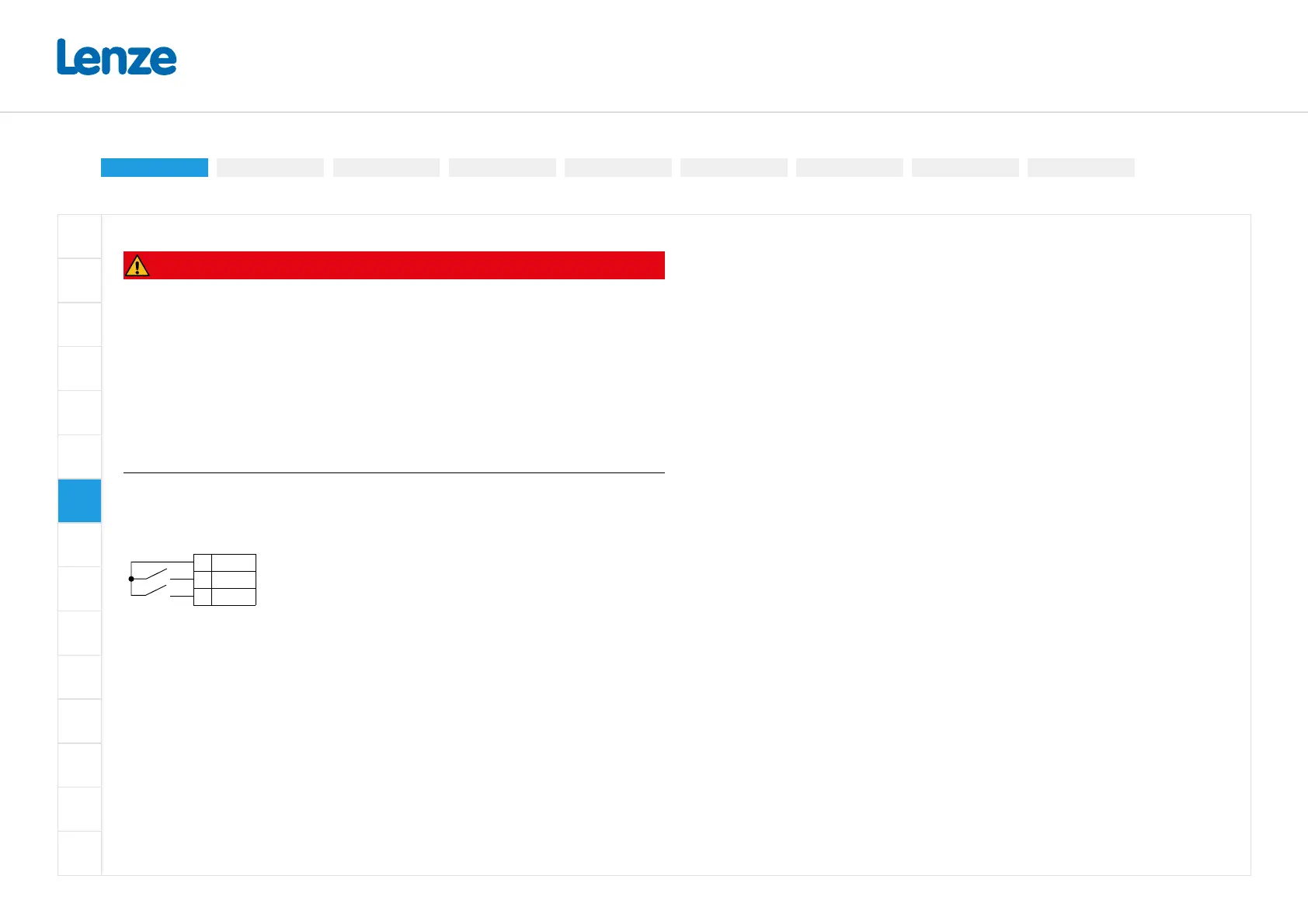
• Connector X3.1 (digital input 1) must be wired.
X3.1
1 24V 24-V output (max. 100 mA)
4 DI1 Start
2 DI2 Reset error (optional)
• The control connections of the safety technology must be wired.
1. Switch on mains voltage.
2. Check readiness for operation.
3. Observe the "DRIVE" LED status display on the front of the inverter.
Carry out functional test
Target: the motor connected to the inverter should rotate as quickly as possible.
Preconditions:
• The connected motor matches the inverter in terms of power.
• The parameter settings correspond to the state upon delivery.
• The inverter is ready for operation. The mains voltage is switched on.
Start the drive and stop it again:
1. Drive enabled: X1/SIA = HIGH and X1/SIB = HIGH
2. Start drive: X3.1/DI1 = HIGH (switch closed)
- The drive rotates with 20 Hz.
3. Stop drive again: X3.1/DI1 = LOW (switch open)
Commissioning
Important notesInitial switch-on
Parameter overviewQuick commissioning
EASY Starter
Additional functions
Basic setting Motor control
Favorites

 Loading...


