Electrical installation
Control connections
4
l
63
EDKLCMZ3024−SPS DE/EN 4.0
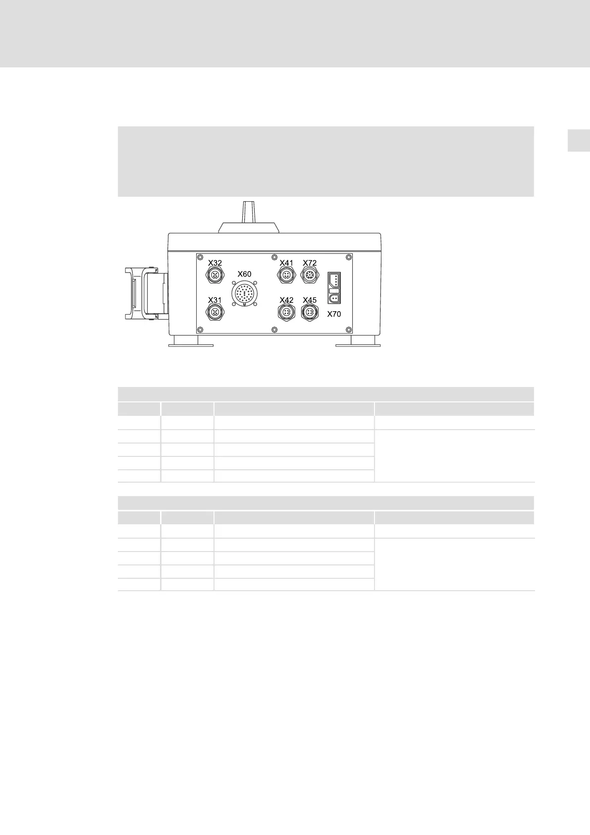
4.6 Control connections
) Note!
The sums of all inputs currents and output currents on X41, X42, X45, X60 and
X72 may be max. 1.3 A.
If the total current is higher, the device switches off!
lcu12x_000e
Digital inputs
X41 − digital inputs E1, E2
Pin Signal Description Data
Connector: socket, 4−pole, M12
1 +24 V Supply
2 Signal 2 E2 HIGH +13 .... 26.5 V DC
3 GND Reference potential LOW 0 ... +4 V
4
Signal 1 E1 8 mA at 24 V DC
X42 − digital inputs E3, E4
Pin Signal Description Data
Connector: socket, 4−pole, M12
1 +24 V Supply
2 Signal 2 E4 HIGH +13 .... 26.5 V DC
3 GND Reference potential LOW 0 ... +4 V
4 Signal 1 E3 8 mA at 24 V DC
 Loading...


