3 RG-SDMOD
Introduction
2 Introduction
This document defines the specifics required for Modbus serial communication with a Lenze-AC Tech
standard
smd
Series drive for control, status monitoring, and programming parameters. A familiarity
with normal drive capabilities and operations is assumed. If this is not the case, refer to the
smd
Series
Operating Instructions (SL03) for more information.
2.1 RS485 Details
Only standard
smd
models with an “L” as the eighth digit in the model number (ex. ESMD371L4TXA) are
equipped with Modbus RS-485 capabilities. When using this feature the drive can communicate with a
personal computer (PC), programmable logic controller (PLC), or other external device that utilizes Modbus
RS-485 serial communication for control or monitoring. Refer to the
smd
Operating Instructions (SL03) for
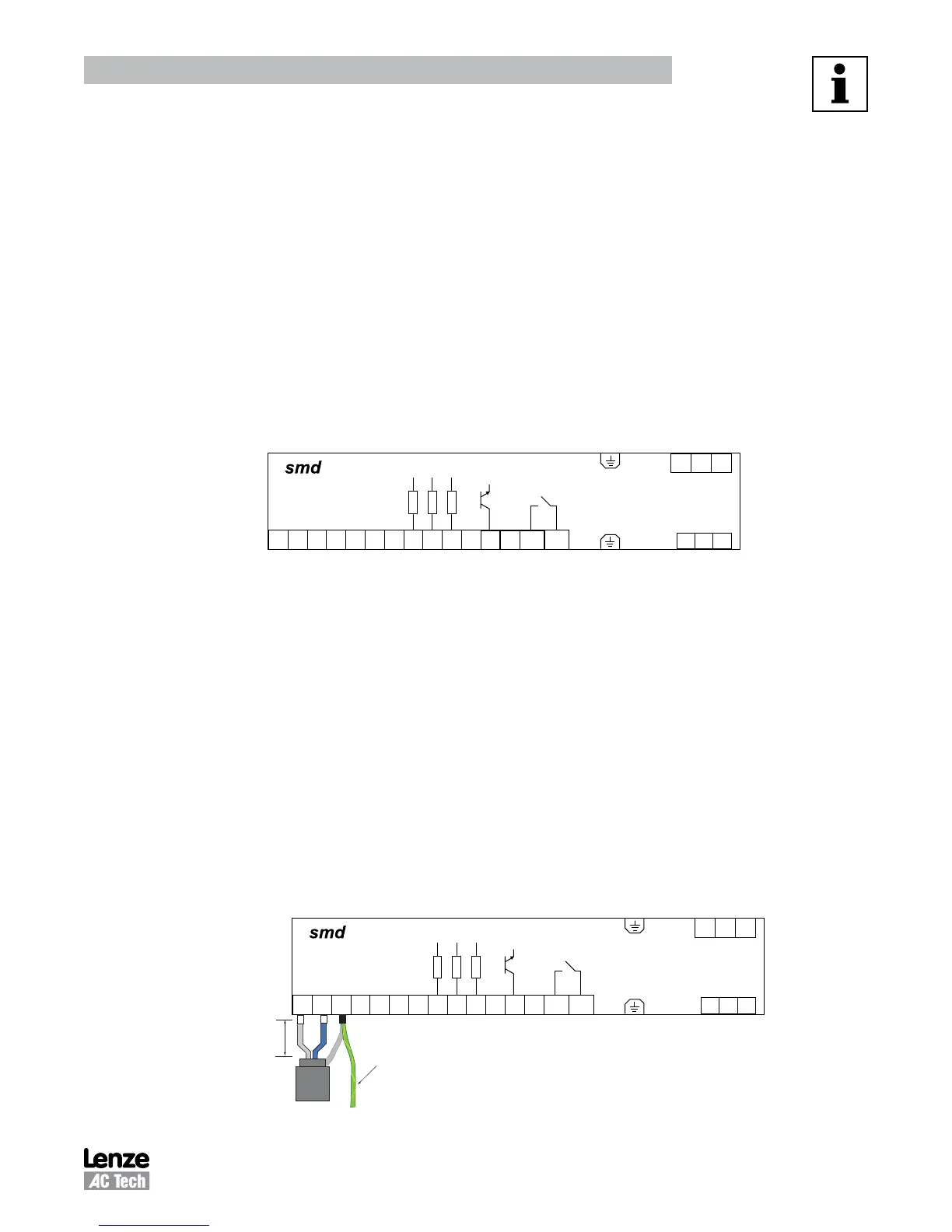
connection details. Figure 1 illustrates the
smd
control strip. Terminals 7 (COM), 71 (TXB) and 72 (TXA) are
used for RS485 communication.
U V W
L1 L2
8 9 20 28 E1
E2
E3
K14
K12
+10 V
+12 V
COM
AIN
771 72
L3
20 A1
62
TXA
TXB
COM
Figure 1:
smd
Control Strip
2.2 Electrical Installation
2.2.1 Cable Type
For RS485 Modbus networks, use a quality shielded twisted pair cable. The use of low quality cable will
result in excess signal attenuation and data loss.
2.2.2 Connections and Shielding
To ensure good system noise immunity all networks cables should be correctly grounded:
• Minimum grounding recommendation: ground the network cable shield once in every cubical.
• Ideal grounding recommendation: ground the network cable on or as near to each drive as possible.
• For wiring of cable to the
smd
control terminal, the unscreened cable cores should be kept as short as
possible; recommended maximum of 20mm. Ground the shield at the drive end only.
• In addition, grounding terminal 7 on the
smd
is recommended when using serial communications.
U V W
L1 L2
8 9 20 28 E1
E2
E3
K14
K12
+10 V
+12 V
COM
AIN
771 72
L3
20 A1
62
TXA
TXB
COM
20mm
max
Connect to
drive earth
(PE)
Figure 2: Connector Wiring Diagram
Phone: 800.894.0412 - Fax: 888.723.4773 - Web: www.clrwtr.com - Email: info@clrwtr.com
 Loading...