SMVector I/O Module ALSV01 v1.0 13376253 14
Commissioning
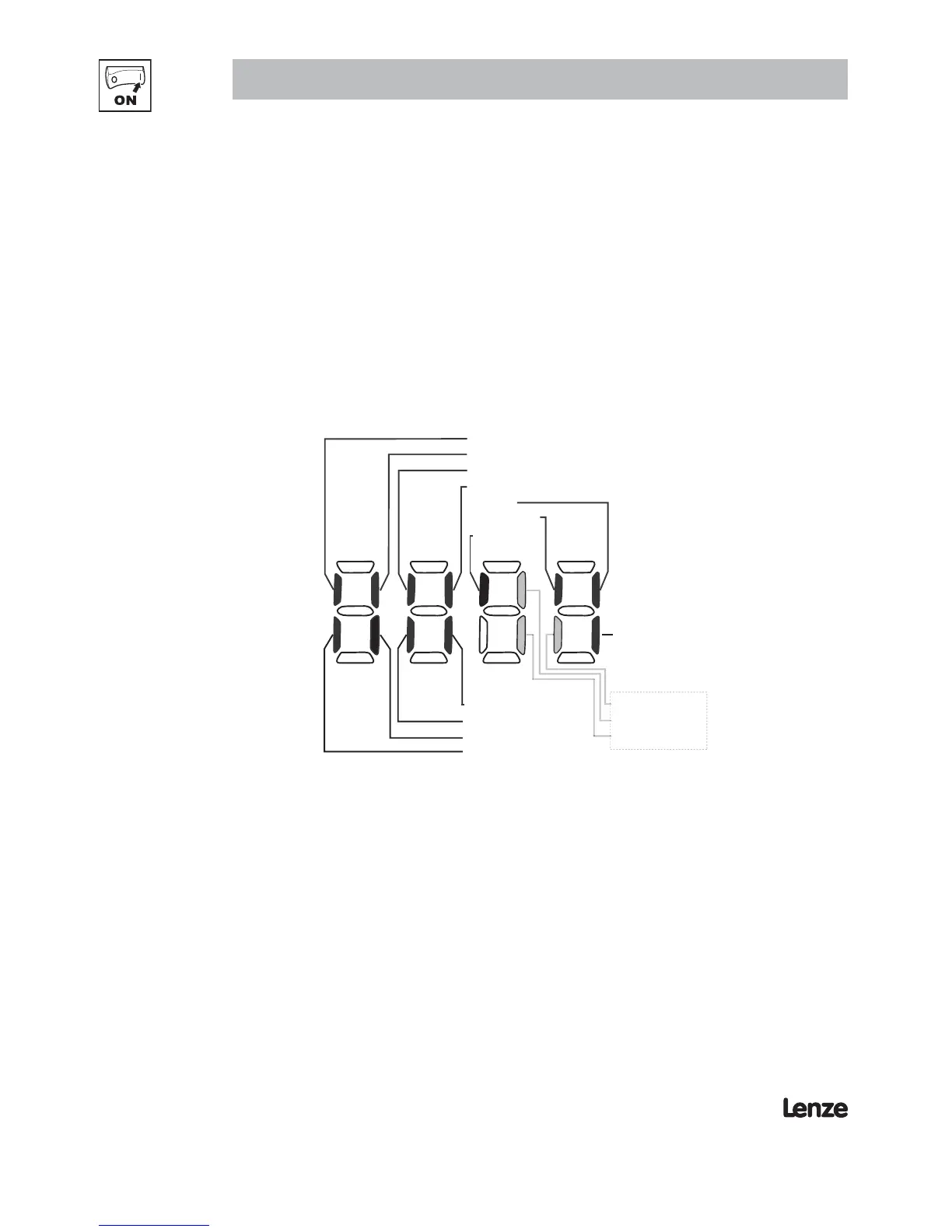
4.3 Display
Parameter P530 allows monitoring of the control terminal points and common drive conditions.
An illuminated LED segment indicates:
• the protective circuit is active (LED 1)
• the Logic Assertion Switch is set to High (+)
• input terminal is asserted (LED 2)
• output terminal is energized (LED 4)
• the Charge Relay is not a terminal, this segment will be illuminated when the Charge Relay is energized
(LED 4).
Input 13C
Input 13A
Factory Reserved
Protective Diagnostic
Current Limit Diagnostic
Logic Assertion Switch
Input 1
Input 13B
Relay
Output 14
Input 13D*
* Input 13D available on 15-60HP (11-45kW) models only
LED #
12
3
4
Charge
Relay
Auxiliary Relay
Input 13F
Input 13E
Additional I/O Module only
Figure 6: Status Indicators
 Loading...