SMVector I/O Module ALSV01 v1.0 13376253 8
Installation
3 Installation
3.1 Mechanical Installation
1. Ensure that for safety reasons the AC supply has been disconnected before opening the terminal
cover.
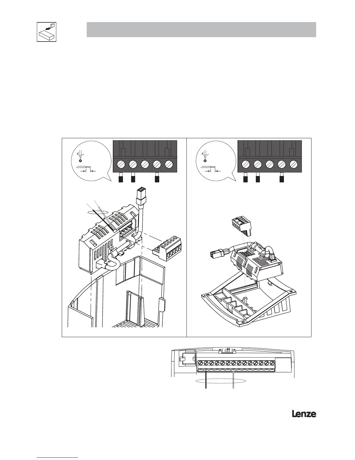
2. Insert the Additional I/O module in the terminal cover and securely “click” into position as illustrated
in Figure 2.
3. Wire the cables to the connector provided and plug the connector into the option module.
4. Align terminal cover for re-fi tting, connect the module umbilical cord to the drive then close the cover
and secure, as shown in Figure 3.
13G
13F
21 20
19
7mm
<_ 2.8 mm²
(12-22 AWG)
0.5 Nm/ 4.5 lb-in
13G
13F
21 20
19
7mm
<_ 2.8 mm²
(12-22 AWG)
0.5 Nm/ 4.5 lb-in
Figure 2a: NEMA 1 (IP31) Installation Figure 2b: NEMA 4X (IP65) Installation
The ESVZAL1 I/O Option Module contains 1 red
wire and 1 black wire that must be wired into the
standard SMVector Inverter terminal strip.
Connect the black wire to terminal #2.
Connect the red wire to terminal #11.
Refer to adjacent diagram.
1256
25
4
11 13A13B 13C
14
30 16 17
Black and Red wires from ESVZAL1 Module
Terminal Strip of Standard SMVector Inverter
Figure 2c: Wiring the
ESVZAL1 I/O Module
 Loading...