20
SV01N_13418587 EN/DE/ES/FR/IT/PT
Installation
Notes for Fuse and Cable Table:
(1) Installations with high fault current due to large supply mains may require a type D circuit breaker.
(2) UL Class CC or T fast-acting current-limiting type fuses, 200,000 AIC, preferred. Bussman KTK-R, JJN or JJS or equivalent.
(3) Thermomagnetic type breakers preferred.
_ 11th digit of part number: F = Integral EMC Filter
L = Integral EMC Filter and Integrated Disconnect Switch (NEMA 4X/IP65 Models only)
M = Integrated Disconnect Switch (NEMA 4X/IP65 Models only)
X = No EMC Filter/ No Disconnect Switch
* = Last digit of part number: C = N4X Indoor only (convection cooled)
E = N4X Indoor/Outdoor (convection cooled)
~ = Last digit of part number: D = N4X Indoor only (fan cooled)
F = N4X Indoor/Outdoor (fan cooled)
Observe the following when using Ground Fault Circuit Interrupters (GFCIs):
• InstallationofGFCIonlybetweensupplyingmainsandcontroller.
• TheGFCIcanbeactivatedby:
- capacitive leakage currents between the cable screens during operation (especially with long, screened motor cables)
- connecting several controllers to the mains at the same time
- RFI filters
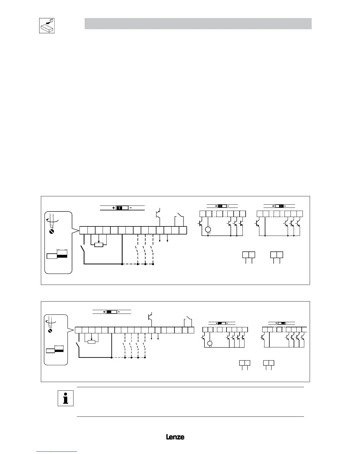
3.2.3 Control Terminals
Control Terminal Strip for 0.33 - 10 HP (0.25 - 7.5 kW):
6 25 4 11
13A
13B
13C
17
5 1 2
14 30
16
AOUT
DIGOUT
2k … 10k
+10 V
AIN
AIN
COM
COM
NOTE
Control and communications terminals provide basic insulation when the drive is connected to a power system rated up
to 300V between phase to ground (PE) and the applied voltage on terminals 16 and 17 is less than 250 VAC between
phase to phase and ground (PE).
 Loading...