EasyManuals Logo

Lenze SX-1 User Manual

Lenze SX-1
168 pages
To Next Page IconTo Next Page
To Previous Page IconTo Previous Page
Page #14 background imageLoading...
Page #14 background image
3-3.1.1
3.1
Positioning System
SX-1
3.1.1
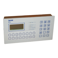
Layout
of
the
SX-1
Mountlng
holes
Metal
case
Ventilation
louvres
Status
single
character display
of
mode and
error
codes
5
Reset:
resets
the
controller
7
6
Ax.Nr:
defines
axis
number.
Updated
by
Power
On
or
Reset
LED
Green:
b.s.
Bus
select
LED
Red:
w.d.:
Watch
Dog
(error)
llluminated
upon
internal
faults
8
Feedback/inc
Feedback/abs
Measuring
System
Connector
X4 for
lncre
-
mental
or
Absolute/Serial
Encoder
9
SerIal
I/O
terminal:
Serial
(Data)
Connector
X3 for
Programming
Terminat/Controller
or
for
Host
Computer
or
PLC
10
Drlve
Control:
Controller
Connector
X2
for
Servo
Reference
signal
and
end-of-travel
and
refe
-
rence switches
11
lnput/Output:
Parallel
Interface
Connector
Xl
for...
12
MaIn
Power
Supply
Connectlon
(under
-
neath)
3/1
1
2
3
4
1
2
12
Lanze

Table of Contents

Questions and Answers:

Question and Answer IconNeed help?

Do you have a question about the Lenze SX-1 and is the answer not in the manual?

Lenze SX-1 Specifications

General IconGeneral
BrandLenze
ModelSX-1
CategoryIndustrial Equipment
LanguageEnglish

Related product manuals