7 - NOMENCLATURE 7 - PARTS
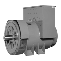
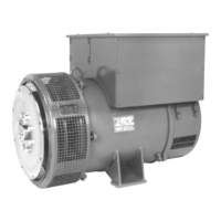
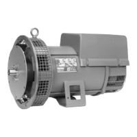
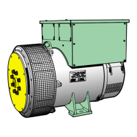
Alternator
LSA 41.1, 41.2, 42.1, 44.1 - 4P
Alternateur
LSA 41.1, 41.2, 42.1, 44.1 - 4P
Rep Nbre Désignation Rep Nbre Désignation
1 1 Ensemble stator 1 1 Wound stator assembly
4 1 Ensemble rotor 4 1 Wound rotor assembly
15 1 Turbine 15 1 Fan
18 1 Disque d'équilibrage 18 1 Balancing discs
21 1 Anneau de levage 21 1 Lifting eye
22 1 Clavette de bout d'arbre 22 1 Key
28 1 Borne de masse 28 1 Earth terminal
30 1 Flasque côté accouplement 30 1 D.E bracket
33 1 Grille de protection 33 1 Air exit screen
34 2 Vis de fixation 34 2 Bolts
36 1 Flasque côté excitatrice 36 1 N.D.E bracket
37 4 Tige de fixation 37 4 Rods
38 4 Ecrou 38 4 Nut
41 1 Partie avant du capotage 41 1 Terminal box panel D.E
48 1 Partie supérieure du capotage 48 1 Terminal box cover
49 12 Vis du capotage 49 12 Screws
51 1 Grille d'entrée d'air 51 1 Air inlet screen
60 1 Roulement avant 60 1 D.E bearing
62 2 Vis de fixation 62 2 Bolts
68 1 Chapeau intérieur 68 1 Inner bearing cap
70 1 Roulement arrière 70 1 N.D.E bearing
79 1 Rondelle élastique 79 1 Spring washers
90 1 Inducteur d'excitatrice 90 1 Wound exciter field
91 4 Vis de fixation 91 4 Bolts
100 1 Induit d'excitatrice 100 1 Wound exciter armature
106 1 Ensemble disque porte diodes (42.1) 106 1 Rotating diode assembly (42.1)
107 1 Support de croissant (41.1)(41.2) 107 1 Rotating diode carrier (41.1)(41.2)
120 1 Semelle 120 1 Terminal plate support
124 2 Planchette à bornes 124 2 Terminal plate
135 1 Joint de capotage 135 1 Sealing
139 1 Joint de capotage 139 1 Sealing
198 1 Régulateur 198 1 A.V.R
199 4 Vis de fixation 199 4 Bolts
284 1 Circlips 284 1 Circlip
320 1 Manchon d'accouplement 320 1 Driving hub
321 1 Clavette du manchon 321 1 Driving hub key
322 2 Disque d'accouplement 322 2 Driving discs
323 5 ou 6 Vis de fixation 323 5 ou 6 Bolts
325 (*) Disque de calage 325 (*) Spacer shim
330 1 Bride d'accouplement 330 1 Coupling flange
343 1 Croissant de diodes directes 343 1 Forward diode assembly
344 1 Croissant de diodes inverses 344 1 Reverse diode assembly
347 1 Varistance de protection (+ C. I.) 347 1 M.O. varistor (on P.C.)
349 1 Joint torique 349 1 Rubber "O ring"
364 1 Support régulateur 364 1 A.V.R. support
365 1 Partie arrière du capotage 365 1 N.D.E. terminal box
367 1 Porte du capotage régulateur 367 1 A.V.R. removable access panels
368 1 Porte du capotage 368 1 Removable access panels
371 4 Amortisseur 371 4 Shock absorber
410 1 Palier ammovible 410 1 D.E. bearing housing
411 6 Vis de fixation 411 6 Bolts
466 1 Porte d'accès régulateur 466 1 A.V.R. removable access panels
 Loading...