13
and F2 buttons.
For more information on connecting to and using Mission Control, see section 9 of this
manual.
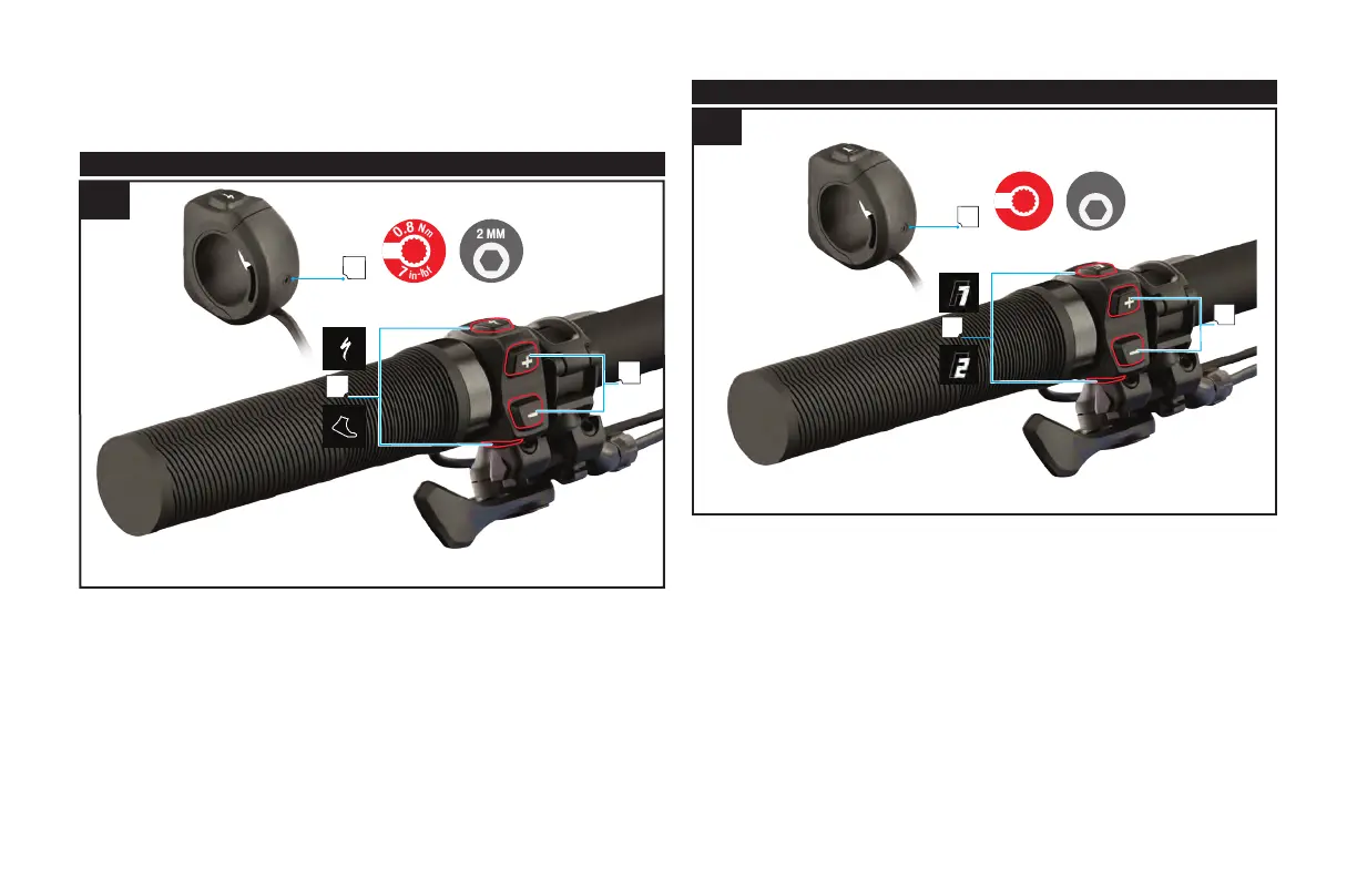
8.3. HANDLEBAR REMOTE (TCU 1)
8.3
Fig. 8.3
The TCU 1 handlebar remote is included on some Levo models and controls the level of motor
support.
A: (+)(-) Support adjustment buttons
B: Function Buttons, pressing and holding the lower function button activates the walk-
assist mode.
C: Compression Screw (2 mm Hex Key 0.8 Nm 7 in-lbf)
8.4. HANDLEBAR REMOTE (TCU 2)
7
i
n
-
l
b
f
0
.
8
N
m
2 MM
B
A
C
8.4
Fig. 8.4
The TCU 2 handlebar remote is included on some Levo models and controls the level of motor
support and controls the functions and scrolling of the TCU 2.
A: (+ -) Support adjustment buttons. (Scrolling and setting up of the TCU 2)
B: Function Buttons F1 and F2 (Scrolling and setting up of the TCU 2) Pressing and holding
the F2 button activates the walk-assist mode.
C: Compression Screw (2 mm Hex Key 0.8 Nm 7 in-lbf).
 Loading...