35
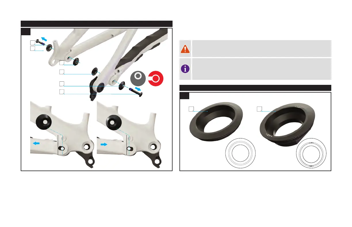
12.1. ADJUSTING THE HORST PIVOT FLIP CHIP
5 MM
9
0
i
n
-
l
b
f
1
0
N
m
A
B
B
B
A
B
12.1
HIGH
LOW
Fig. 12.1
Remove the Horst pivot bolt from the frame (A).
Remove all four flip-chips (B) and align the Horst Pivot spacer in the slot to either "high" or
"low" position. When replacing the adjustable spacer make sure it is correctly located into
the chainstay and that both parts of the flip-chip are aligned in the same direction.
Reinstall the flip chips in the desired high or low position. Make sure they are fully seated
and aligned with the chain-stay protector before tightening the bolt.
Torque the Pivot bolt to 10 Nm / 90 in-lbf.
WARNING: The drive side and non-drive side Horst flip chips must both be
aligned in the same high or low position. Improperly installed Horst flip chips
can damage the frame and can also cause you to lose control and fall.
INFO: All models are assembled with the Flip Chip in the high position.
Switching to the low position lowers the bottom bracket height by
approximately 7 mm and slackens the head tube angle by approximately 0.5
degrees.
12.2. ADJUSTING THE HEAD TUBE ANGLE
A B
0° +/-1°
-1°
+1°
12.2
Fig. 12.2
The head-tube angle is adjustable via adjustable headset cups. The bicycle ships with the
"zero" offset cup (A) and a +/- 1-degree headset cup (B) ships in the small parts box.
 Loading...