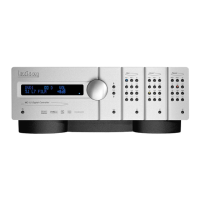
Lexicon
5-13
For example a bad capacitor may produce a high level of distortion and a frequency response problem. The
frequency response problem would be easier to trace because the signal level can be monitored throughout
the signal path on an ordinary oscilloscope.
All cable connectors mounted to the main board should be verified for proper, intermittent-free operation
and continuity.
One Bad Channel
One of the most useful pieces of information is determining whether a problem occurs on one or all
channels. If the problem occurs at only one output, the following assumption can be made with some level
of confidence:
1. The power supplies are OK.
2. System timing (clocks) are OK.
3. The digital circuitry (with the exception of the A/D and D/A converters circuitry) are OK.
These problems can be fairly easy to troubleshoot, as the working channel can be used as a reference to
test the bad channel. With the same signal applied to both inputs, comparing the signals on both channels
at various points along the analog path will help in localizing the problem fairly quickly.
Diagnostics may be helpful in isolating RAM or DSP failures that might cause bad audio. Refer to the
diagnostics Description for more information.
All Channels Bad
The fact that a problem occurs in all channels can be revealing, as the likelihood of two or more separate
components failing in the same way at the same time is remote. The problem is likely to be with a
component or components common to all channels. Another likely cause is a defective power supply. Verify
that the power supplies are operational and within specification.
No Output
If there is no output from only one channel, the problem can easily be traced by comparing the signals at
various points along the analog signal path with a functioning channel.
If there is no output from any channel, check the +/- 15 Volt analog and +/- 5 Volt analog supplies to verify
that they are operational and within specification. If the power supplies are OK, determine whether the
problem lies within the A/D conversion or the D/A conversion, then troubleshoot the appropriate circuitry.
Video Problems
Determine if the problem exists with all video inputs or outputs, with only certain types of video inputs or
outputs (composite or S-video) or with only a single video input or output.
Verify that there is reliable continuity between all of the rear panel connectors and the video connector on
the board. (Note that the S-video input and output connectors are mounted directly on the video board.) For
composite video problems, verify the connectors from the video connector board (J612) to the main board
(J12).
If the problem exists with only one connection or type of input/output, troubleshooting the associated
circuitry on the video board. If the problem exists with all video inputs and outputs, verify the connections
from the video board (J13) to the main board (J23) and /or troubleshooting the associated main board
interface.
 Loading...