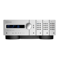
MC-1 Service Manual
5-14
Power Supply
Initial Tests
Note: The main power supply in the MC-1 has an operational range of 90-240 VAC, 50-60 Hz 35 Watts.
The following test is for North American Line Voltage of 120 VAC.
1. Set the variable AC supply to 0 volts.
2. Connect the power cord between the supply and the MC-1
3. Turn the MC-1 rear panel Power switch On and slowly bring up the voltage to 120VAC. The current
should not exceed 0.3 Amps for 100/120 Volts testing (0.15 Amps for 220/240 Volts). If the unit draws
excessive current, turn the MC-1 off and check the supply rails for shorts.
4. Use a DMM to measure all the power supply rails by using the MC-1 chassis ground as the 0VDC
reference. Verify that all voltages are within the tolerance range shown below.
Battery Test:
Turn the MC-1 rear panel Power switch OFF. Locate (U72 SRAM) on the Right side of the Main Board.
With a DVM meter place the black lead on the chassis and place the Red lead on the far-Left pin of U72.
Verify the voltage is >2.50 VDC.
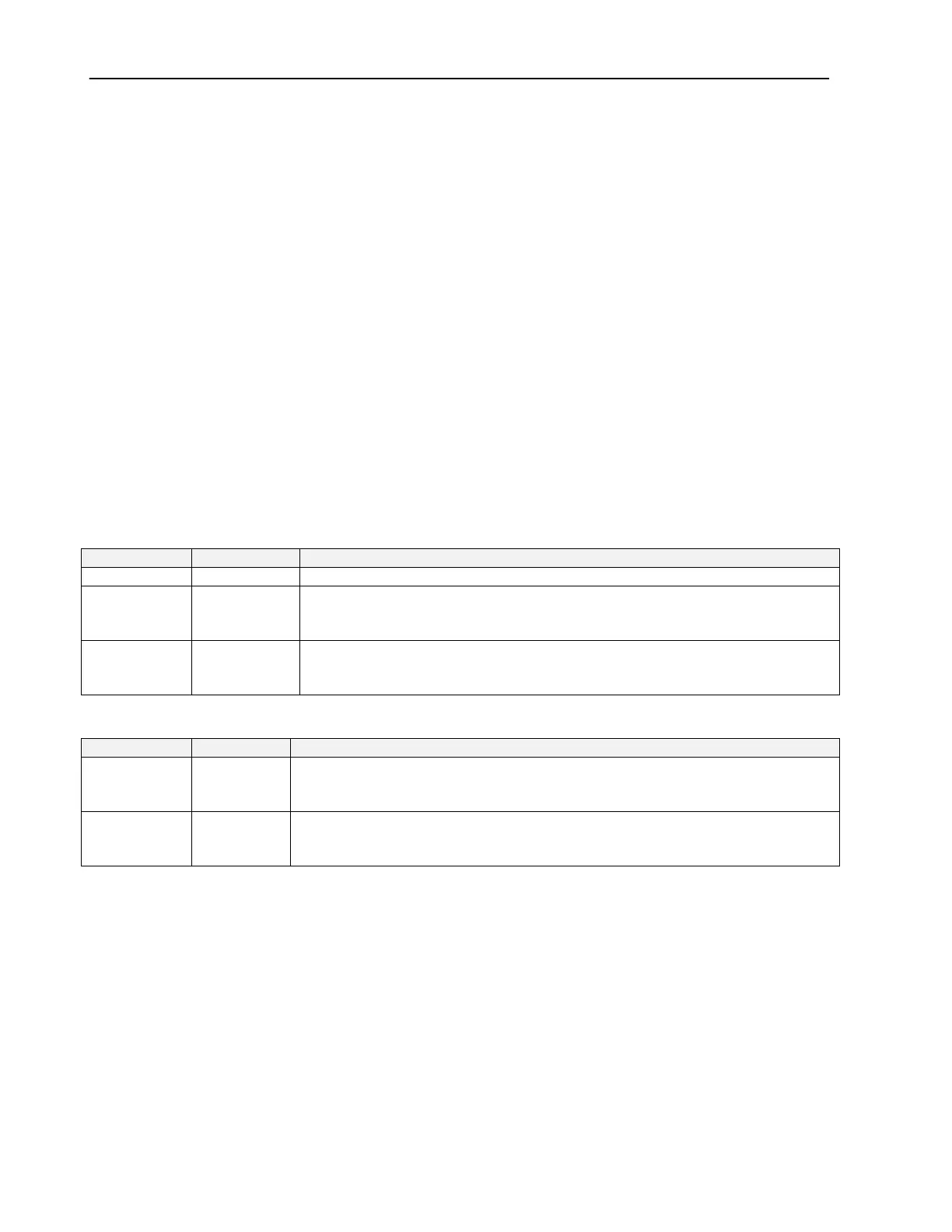
Main Board
Supply Rail Tolerance Location
+5 VD 4.94-5.26 Front Left corner near Red wires soldered at J26
+15 V 15.00-16.95 Located test points marked (+15V) on the Main board just above U65 right
side middle on the board. A marked Ground Test point can be found to the
Left of U44.
-15 V 14.25-15.75 Located test points marked (-15V) on the Main board just above U65 right
side middle on the board. A marked Ground Test point can be found to the
Left of U44.
Video Board
Supply Rail Tolerance Location
+5VA 4.75-5.25 Located test points marked (+5VA) on the Main board just above U65 right
side middle on the board. A marked Ground Test point can be found to the
Left of U44.
-5VA 4.75-5.25 Located test points marked (-5VA) on the Main board just above U65 right
side middle on the board. A marked Ground Test point can be found to the
Left of U44.
 Loading...